 Honda Accord: Body Electrical
Special Tools

General Troubleshooting Information
Tips and Precautions
Special Tools Required
Back Probe Adapter, 17 mm 07TAZ-001020A
1. Check applicable fuses in the appropriate fuse/relay box.
2. Check the battery for damage, state of charge, and clean and tight connections.

• Do not quick-charge a battery unless the battery ground cable has been disconnected, otherwise you will damage the alternator diodes.
• Do not attempt to crank the engine with the battery ground cable loosely connected or you will severely damage the wiring.
Handling Connectors
• Make sure the connectors are clean and have no loose wire terminals.
• Make sure multiple cavity connectors are packed with dielectric grease (except watertight connectors).
• All connectors have push-down release type locks (A).
• Some connectors have a clip on their side used to attach them to a mount bracket on the body or on another component. This clip has a pull type lock.
• Some mounted connectors cannot be disconnected unless you first release the lock and remove the connector from its mount bracket (A).

• Never try to disconnect connectors by pulling on their wires; pull on the connector halves instead.
• Always reinstall plastic covers.
• Before connecting connectors, make sure the terminals (A) are in place and not bent.
• Check for loose retainers (A) and rubber seals (B).

• The backs of some connectors are packed with dielectric grease. Add grease if necessary. If the grease is contaminated, replace it
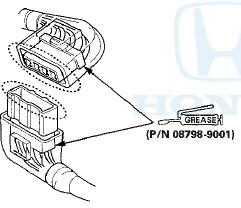
• Insert the connector all the way and make sure it is securely locked.
• Position wires so that the open end of the cover faces down.
Handling Wires and Harnesses
• Secure wires and wire harnesses to the frame with their respective wire ties at the designated locations.
• Remove clips carefully; don't damage their locks (A).
• After installing harness clips, make sure the harness doesn't interfere with any moving parts.
• Keep wire harnesses away from exhaust components and other hot parts, from sharp edges of brackets and holes, and from exposed screws and bolts.
• Seat grommets in their grooves properly (A). Do not leave grommets distorted (B).

Testing and Repairs
• Do not use wires or harnesses with broken insulation.
Replace them or repair them by wrapping the break with electrical tape or shrink tubing.
• Never attempt to modify, splice, or repair SRS wiring.
If there is an open or damage is SRS wiring or terminals, replace the harness.
• After installing parts, make sure that no wires are pinched under them.
• When using electrical test equipment, follow the manufacturer's instructions and those described in this manual.
•If possible, insert the probe of the tester from the wire side (except waterproof connector).
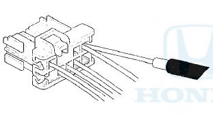
• Use back probe adapter, 17 mm 07TAZ-001020A.

• Refer to the instructions in the Honda Terminal Kit for identification and replacement of connector terminals.
Five-step Troubleshooting
1. Verify The Complaint: Turn on all the components in the problem circuit to verify the customer complaint. Note the symptoms.
Do not begin disassembly or testing until you have narrowed down the problem area.
2. Analyze The Schematic: Look up the schematic for the problem circuit.
Determine how the circuit is supposed to work by tracing the current paths from the power feed through the circuit components to ground. If several circuits fail at the same time, the fuse or a ground is a likely cause.
Based on the symptoms and your understanding of the circuit operation, identify one or more possible causes of the problem.
3. Isolate The Problem By Testing The Circuit: Make circuit tests to check the diagnosis you made in step 2. Keep in mind that a logical, simple procedure is the key to efficient troubleshooting. Test for the most likely cause of failure first. Try to make tests at points that are easily accessible.
4. Fix The Problem: Once the specific problem is identified, make the repair. Be sure to use proper tools and safe procedures.
5. Make Sure The Circuit Works: Turn on all components in the repaired circuit in all modes to make sure you've fixed the entire problem.
If the problem was a blown fuse, be sure to test all of the circuits on the fuse. Make sure no new problems turn up and the original problem does not recur.
Wire Color Codes
The following abbreviations are used to identify wire colors in the circuit schematics:
WHT-White
YEL -Yellow
BLK -Black
BLU -Blue
GRN -Green
RED-Red
ORN- Orange
PNK- Pink
BRN -Brown
GRY -Gray
PUR -Purple
T A N - Tan
LT BLU -Light Blue
LT GRN -Light Green
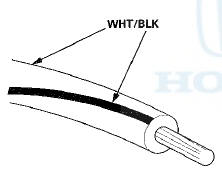
The wire insulation has one color or one color with another color stripe. The second color is the stripe.
How to Check for DTCs with the Honda Diagnostic System (HDS)
NOTE: For specific operations, refer to the user's manual that came with the Honda Diagnostic System (HDS).
Make sure the HDS is loaded with the latest software.
1. Connect the HDS to the data link connector (DLC) (A) located under the driver's side of the dashboard.
2. Turn the ignition switch to ON (II).
3. Make sure the HDS communicates with the vehicle; if it does not troubleshoot the DLC circuit (see page 11-181).
4. Enter the BODY ELECTRICAL then select the desired MODE MENU.
5. Check for DTCs with the HDS.
NOTE: If the DTCs do not pertain to the selected menu, select the All DTC Check icon to view all Body Electrical DTCs.
6. If any DTCs are indicated, note them, and go to the indicated DTC troubleshooting.
- Relay and Control Unit Locations
- Connectors and Harnesses
- Fuse/Relay Boxes
- Power Distribution
- Ground Distribution
- Under-hood Fuse/Relay Box
- Under-dash Fuse/Relay Box
- Battery
- Relays
- Ignition Switch
- Multiplex Integrated Control System
- Keyless/Power Door Locks/Security System
- Horns
- Exterior Lights
- Turn Signal/Hazard Warning Lights
- Interior Lights
- Entry Lights Control System
- Power Windows
- Wipers/Washers
- Gauges
- Safety Indicator System
- Reminder Systems
- Moonroof
- Accessory Power Sockets
- Power Mirrors
- Automatic Dimming Inside Mirror
- Power Seats
- Power Lumbar Support
- Seat Heaters
- Rear Window Defogger
- Immobilizer System
 Climate Control Switch
Removal / Installation
Climate Control Switch
Removal / Installation
With Navigation
1 Remove the audio unit (see page 23-114).
2. Remove the self-tapping screws and the climate
control switches (A). If necessary, replace the bulbs
(B).
3. Install the switches ...

See also:
Frame Brace Replacement
Strut Brace Replacement
1. Remove the cowl cover (see page 20-278).
2. Disconnect the brake booster vacuum hose (A) from
the strut brace (B).
3. Remove the nuts from the top of the damper, and ...
Using Automatic Climate Control
The automatic climate control system maintains the interior temperature you
select.
The system also selects the proper mix of heated or cooled air that will as
quickly as
possible, raise or l ...
General Troubleshooting
Information
Lever-Locked Connector
Disconnecting
To disconnect the connector, pull the lever (A) while
pushing the lock tab (B) down, then pull the connector
(C).
Connecting
To connect the connector, push ...