 Honda Accord: Piston Installation
If the Crankshaft is Already Installed
1. Set the crankshaft to bottom dead center (BDC) for each cylinder as its piston is installed.
2. Remove the connecting rod caps, then install the ring compressor, and check that the bearing is securely in place.
3. Apply new engine oil to the piston, the inside of the ring compressor, and the cylinder bore, then attach the ring compressor to the piston/connecting rod assembly.
4. Position the mark (A) to face the cam chain side of the engine block.
5. Position the piston in the cylinder, and tap it in using the wooden handle of a hammer (A).
Push down on the ring compressor (B) to prevent the rings from expanding before entering the cylinder bore.
8. Stop after the ring compressor pops free, and check the connecting rod-to-rod journal alignment before pushing the piston into place.
7. Check the connecting rod bearing clearance with plastigage (see page 7-9).
8. Inspect the connecting rod bolts (see page 7-28).
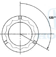
9. Apply new engine oil to the bolt threads, then install the connecting rod caps with bearings. Torque the bolts to 41 N-m (4.2 kgfm, 30 Ibf-ft).
10. Tighten the connecting rod bolts an additional 120 Р’В°.
NOTE: Remove the connecting rod bolt if you tightened it beyond the specified angle, and go back to step 8 of the procedure. Do not loosen it back to the specified angle.
If the Crankshaft is Not Installed
1. Remove the connecting rod caps, then install the ring compressor, and check that the bearing is securely in place.
2. Apply new engine oil to the piston, the inside of the ring compressor, and the cylinder bore, then attach the ring compressor to the piston/connecting rod assembly.
3. Position the mark (A) to face the cam chain side of the engine block.
4. Position the piston in the cylinder, and tap it in using the wooden handle of a hammer (A).
Push down on the ring compressor (B) to prevent the rings from expanding before entering the cylinder bore.
5. Position all pistons at top dead center (TDC).
 Piston Ring Replacement
1. Remove the piston from the engine block (see page
7-14).
2. Using a ring expander (A), remove the old piston
rings (B).
3. Clean all ring grooves thoroughly with a squared-off
broken ring ...
 Connecting Rod Bolt Inspection
1. Measure the diameter of each connecting rod bolt at
point A and point B.
2. Calculate the difference in diameter between point A
and point B.
Point A-”Point B = Difference in Diameter
D ...
See also:
Windshield Washers
Check the level in the windshield
washer reservoir at least monthly
during normal use.
Check the fluid level by removing
the cap and looking at the level
gauge.
On Canadian models: The low ...
Wheel Alignment
The suspension can be adjusted for front and rear toe.
Pre-Alignment Checks
For proper inspection and adjustment of the wheel ;
alignment, do these checks:
1. Release the parking brake-to avoid an ...
Auto Door Locking/Unlocking
Your vehicle locks and unlocks all doors automatically when a certain
condition is
met.
• Auto Door Locking
• Drive lock mode
All doors lock when the vehicle’s speed reaches about 10 mph ...