 Honda Accord: Crankshaft Main Bearing Replacement
Main Bearing Clearance Inspection
1. To check the main bearing-to-journal oil clearance, remove the lower block and the bearing halves (see page 7-14).
2. Clean each main journal and the bearing half with a clean shop towel.
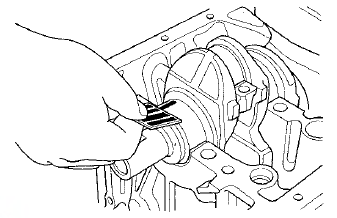
3. Place one strip of plastigage across each main journal.
4. Reinstall the bearings and the lower block, then torque the bolts to 29 N-m (3.0 kgf-m, 22 Ibfft).
NOTE: - Apply new engine oil to the bolt threads and flanges.
- Do not rotate the crankshaft during inspection.
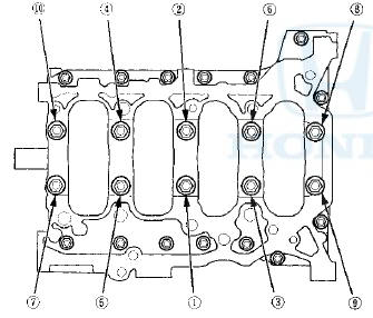
5. Tighten the bearing cap bolts an additional 48 Р’В°.
6. Remove the lower block and the bearings again, and measure the widest part of the plastigage.
Main Bearing-to-Journal Oil Clearance
No. 1,2,4,5 Journals:
Standard (New): 0.017-0.041 mm
(0.0007-0.0016 in)
Service Limit: 0.050 mm (0.0020 in)
No. 3 Journal:
Standard (New): 0.025-0.049 mm
(0.0010-0.0019 in)
Service Limit: 0.055 mm (0.0022 in)
7. If the plastigage measures too wide or too narrow, remove the crankshaft, and remove the upper half of the bearing. Install a new, complete bearing with the appropriate color code(s), and recheck the clearance.
Do not file, shim, or scrape the bearings or the caps to adjust clearance.
8. If the plastigage shows the clearance is still incorrect, try the next larger or smaller bearing (the color listed above or below the current one), and check again. If the proper clearance cannot be obtained by using the appropriate larger or smaller bearings, replace the crankshaft and start over.
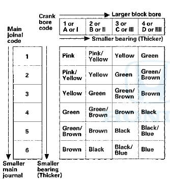
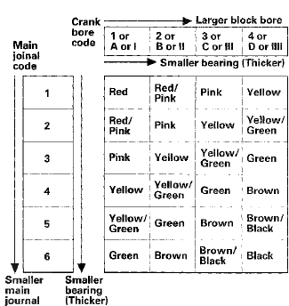
Main Bearing Selection
Crankshaft Bore Code Location
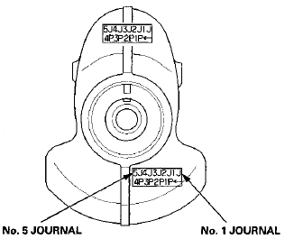
1. Numbers, letters, or bars have been stamped on the end of the lower block as a code for the size of each of I the five main journal bores. Write down the crank bore codes.
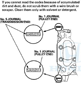
Main Journal C o d e Location
2. The m a i n J o u r n a l c o d e s a r e stamped on the crankshaft in either location.
3. Use the crank bore codes and the crank journal codes to select the appropriate replacement bearings from the following table.
NOTE: - The color code is on the edge of the bearing.
- When using bearing halves of different colors, it does not matter which color is used in the top or bottom.
K24Z2 engine
K2423 engine
 Connecting Rod and Crankshaft End Play Inspection
1. Remove the oil pump (see page 8-16).
2. Remove the baffle plate (see step 8 on page 7-14).
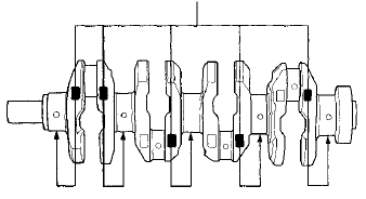
3. Measure the connecting rod end play with a feeler
gauge between the connecting rod and the
cran ...
 Connecting Rod Bearing Replacement
Connecting Rod Bearing Clearance Inspection
1. Remove the oil pump (see page 8-17).
2. Remove the baffle plate (see step 8 on page 7-14).
3. Remove the connecting rod cap and the bearing half.
...
See also:
Speaker Test/Replacement
Front Door Speaker
1. Remove the door panel.
• 4-door (see page 20-17)
• 2-door (see page 20-12)
2. Remove t h e bolt (A). Then lift the speaker straight up
to release t h e lower cli ...
Menu Display
To select any setting such as the
clock, sound adjusting, or the
compass (if equipped), press the
MENU button. To use any audio
system function, the ignition switch
must be in the ACCESSORY ...
Damper/Spring Removal and Installation
Removal
1. Raise and support the vehicle (see page 1-13).
2. Remove the rear wheel.
3. Fold down the rear seat-back, then remove the lid (A).
NOTE: For 4-door, lift up the tab (B) inside und ...