 Honda Accord: Cable Reel Replacement
Removal
1. Make sure t h e f r o n t w h e e l s are a l i g n e d straight ahead.
2. Do t h e b a t t e r y t e r m i n a l d i s c o n n e c t i o n procedure (see page 22-91), t h e n w a i t at least 3 minutes.
3. Remove t h e d r i v e r ' s a i r b a g (see p a g e 24-211).
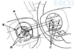
4. Disconnect t h e c a b le reel subharness 20P connector (A) f r om t h e c a b le reel, t h e n r e m o v e t h e s t e e r i ng wheel bolt (B).
5. C o n f i rm t h a t t h e f r o n t w h e e l s point straight ahead, t h e n remove t h e s t e e r i n g wheel w i t h a s t e e r i n g wheel puller (see page 17-6). D o not t a p o n t h e s t e e r i ng wheel o r s t e e r i ng c o l u m n shaft w h e n r e m o v i n g t he steering w h e e l.
6. Remove the upper and lower column covers (see page 20-181).
7. Disconnect the dashboard wire harness 4P connector (A) from the cable reel 4P connector (B), then disconnect the dashboard wire harness 20P connector (C) from the cable reel (D).
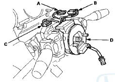
8. Release the lock tab (A) under the cable reel connector with a 90 В° hook shaped tool (B). Slide the tool below the cable reel connector just above the lock tab.
Release the lower lock tab (C), and slide the cable reel off the column.
Installation
1. Before installing the steering wheel, make sure front wheels are aligned straight ahead.
2. If not already done, disconnect the negative cable from the battery, then wait at least 3 minutes.
3. Set the turn signal canceling sleeve (A) so that the projections (B) are aligned vertically.
4. Carefully install the cable reel (A) on the steering column shaft. Then connect the disconnect the dashboard wire harness 20P connector (B) to the cable reel, and connect the cable reel 4P connector (C) to the dashboard wire harness 4P connector (D).
5. Install the upper and lower column covers (see page 20-181).
6. Before Installing the steering wheel, make sure the front wheels are pointing ahead, then center the cable reel (A). Do t h i s by first rotating the cable reel clockwise until it stops. Then rotate it" counterclockwise ^(iabout t h r e e turns) until the arrow mark (B) on the cable reel label points straight up.
7. Position the two tabs (A) of the turn signal canceling sleeve-(B) as shown, and install the. steering wheel on to the steering column shaft, making sure the steering wheel hub '(C) engages the pins (D) of the cable reel and tabs of the turn signal canceling sleeve. Do not' tap on the steering wheel or steering column shaft when installing the steering wheel.
8. Install the steering wheel bolt (A), and tighten it to the specified torque, then connect the cable reel subharness 20P connector (B).
9. Install t h e d r i v e r ' s a i r b a g (see page 24-211).
10. D o t h e b a t t e r y t e r m i n a l reconnection procedure (see page 22-91).
11 Clear any DTCs w i t h t h e HDS (see page 24-38).
12. A f t e r i n s t a l l i n g t h e cable reel, c o n f i rm proper system o p e r a t i o n : • Turn t h e ignition switch t o O N (II); t h e SRS indicator s h o u l d c o m e o n f o r about.6 seconds a n d t h e n go off. • After t h e SRS indicator has t u r n e d off, t u r n t he s t e e r i n g wheel f u l l y left a n d r i g h t t o c o n f i rm t h e SRS indicator does not c o m e on.
• Make s u r e t h e h o r n a n d t u r n signal switches work p r o p e r l y .
• Make s u r e t h e s t e e r i n g wheel switches work p r o p e r l y .
 Airbag and Tensioner Disposal
Special Tools Required
Deployment Tool 07HAZ-SG00500
Before scrapping any airbags, side airbags, side curtain
airbags, seat belt tensioners, (including those in a whole
vehicle to be scrapped), th ...
 SRS Unit Replacement
Removal
1. Do t h e b a t t e r y t e r m i n a l d i s c o n n e c t i o n procedure
(see
page 22-91), t h e n w a i t at least 3 m i n u t e s before
s t a r t i n g work.
2. Remove t h e d ...
See also:
Countershaft Reverse Selector Hub and
3rd Gear Installation
Special Tools Required
Driver Handle, 40 mm I.D. 07746-0030100
1. Install 2nd gear, 1st gear, 5th gear, and the
37 x 41 x 54.3 mm collar on the countershaft.
2. Slide 3rd gear (A) over the count ...
DTC Troubleshooting
DTC P062F: Powertrain Control Module (PCM)
Internal Control Module Keep Alive Memory
(KAM) Error
NOTE: Before you troubleshoot record all freeze data
and any on-board snapshot with the HDS, and re ...
Fuel Tank Unit Removal and
Installation
Special Tools Required
Fuel Sender Wrench 07AAA-S0XA100
Removal
1. Relieve the fuel pressure (see page 11-306).
2. Remove the fuel fill cap.
3. Remove the rear seat cushion (see page 20-241). ...