 Honda Accord: SRS Unit Replacement
Removal
1. Do t h e b a t t e r y t e r m i n a l d i s c o n n e c t i o n procedure (see page 22-91), t h e n w a i t at least 3 m i n u t e s before s t a r t i n g work.
2. Remove t h e d r i v e r ' s a n d passenger's dashboard center l o w e r cover (see page 20-170).
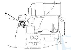
3. Remove t h e TORX bolt (A) u s i n g a TORX T30 bit.
4. Remove t h e a u d i o disc changer ( w i t h navigation system) (see page 23-118) or center pocket (without n a v i g a t i o n system) (see page 20-168).
5. Disconnect SRS u n i t connectors A (39P) a n d B (39P) f r o m t h e SRS unit (C).
NOTE: T h e SRS u n i t connectors have lever locks.
Release t h e locks before d i s c o n n e c t i n g t he connectors (see page 24-30).
6. Remove t h e TORX bolts (D) u s i n g a TORX T30 bit, then pull out the SRS unit.
Installation
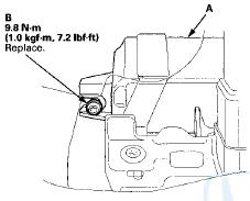
1. Install t h e SRS u n i t (A) w i t h a n e w TORX bolt (B),using a TORX T30 bit.
NOTE: Be s u r e t h e SRS u n i t is s i t t i ng squarely against it's bracket before torquing the TORX bolt.
2. Install t h e n e w TORX bolts (A) u s i n g a TORX T30 b i t t h e n connect t h e connectors (B) t o t h e SRS unit (C); push t h em i n t o p o s i t i on until t h e y click (see page 24-30).
3. Do t he battery terminal reconnection procedure (see page 22-91).
4. Make sure t h e SRS unit has t h e latest software. If it does not have t h e latest, update t h e software in t he SRS unit (see page 24-39).
5. Do t he ODS unit initialization (see page 24-40).
6. Check t he o p e r a t i o n of t h e ODS u n i t w i t h t h e HDS (see page 24-41).
7. C o n f i rm proper SRS o p e r a t i o n : T u r n t h e i g n i t i on switch t o ON (II); t h e SRS indicator s h o u l d c o m e on f o r about 6 seconds and t h e n g o off.
8. Reinstall all removed parts.
 Cable Reel Replacement
Removal
1. Make sure t h e f r o n t w h e e l s are a l i g n e d straight
ahead.
2. Do t h e b a t t e r y t e r m i n a l d i s c o n n e c t i o n procedure
(see
page 22-91), t h e n w a i ...
 Side Impact Sensor (First) Replacement
4-Door
Removal
1. Do t h e battery t e r m i n a l d i s c o n n e c t i o n procedure (see
page 22-91), t h e n w a i t at least 3 m i n u t e s before
s t a r t i ng work.
2. Remove t h e B-p ...
See also:
Information Display
The information display shows the odometer, trip meter, engine oil life and
maintenance service item codes, and other gauges.
• Switching the Display
Press the (Select/Reset) knob to
change th ...
Fuel Pressure Relieving
Before disconnecting fuel lines or hoses, relieve
pressure from the system by disabling the fuel pump,
running the engine until it stalls, then and disconnecting
the fuel line/quick connect fitting ...
Rear Brake Caliper Overhaul
Frequent inhalation of brake pad dust, regardless of material composition,
could be hazardous to your health.
- Avoid breathing dust particles.
- Never use an air hose or brush to clean brake ...