 Honda Accord: Camshaft Inspection
NOTE: Do not rotate the camshaft during inspection.
1. Remove the cylinder head (see page 6-76).
2. Disassemble the rocker arm assembly (see page 6-82).
3. Remove the rocker arm assembly (see page 6-81).
4. Put the rocker shaft holders, the camshaft, and the camshaft holders on the cylinder head, then tighten the bolts, in sequence, to the specified torque.
NOTE: If the engine does not have bolt Р’В© , skip it and continue the torque sequence.
Specified Torque
8 x 1.25 mm 22 N-m (2.2 kgf-m, 16 Ibf-ft)
6x1.0 mm 12 N-m (1.2 kgfm, 8.7 Ibf-ft)
6x1.0 mm Bolts: ,
,
,

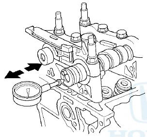
5. Seat the camshaft by pushing it away from the camshaft pulley end of the cylinder head.
6. Zero the dial indicator against the end of the camshaft, then push the camshaft back and forth, and read the end play. If the end play is beyond the service limit, replace the cylinder head and recheck. If it is still beyond the service limit, replace the camshaft.
Camshaft End Play
Standard (New): 0.05-”0.20 mm (0.002-0.008 in)
Service Limit: 0.4 mm (0.02 in)
7. Loosen the camshaft holder bolts two turns at a time, in a crisscross pattern. Then remove the camshaft holders from the cylinder head.
8. Lift the camshafts out of the cylinder head, wipe them clean, then inspect the lift ramps. Replace the camshaft if any lobes are pitted, scored, or excessively worn.
9. Clean the camshaft journal surfaces in the cylinder head, then set the camshafts back in place. Place a plastigage strip across each journal.
10. Install the camshaft holders, then tighten the bolts to the specified torque as shown in step 4.
11. Remove the camshaft holders. Measure the widest portion of plastigage on each journal.
- If the camshaft-to-holder clearance is within the service limits, go to step 13.
- If the camshaft-to-holder clearance is beyond the service limit,;and the camshaft has been replaced, replace the cylinder head. - - If the camshaft-to-holder clearance is beyond the * service limit, and the camshaft has not been replaced, go to step 12.
Camshaft-to-Holder Oil Clearance
Standard (New):
No. 1 Journal: В§.В§3В§-”i.OSS mm
(0.0012-0.0027 in)
No. 2,3,4,5 Journals: 0.060'-”0.099 mm
(0.0024*-0.0039ln)
Service Limit: 0.15 mm (0.006 in)
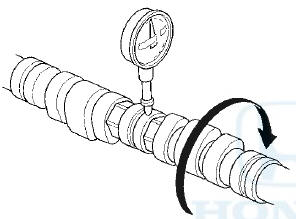
12. Check the total runout with the camshaft supported on V-blocks.
- If the total runout of the camshaft is within the service limit, replace the cylinder head.
- If the total runout is beyond the service limit, replace the camshaft and recheck the camshaft-to-holder oil clearance. If the oil clearance is still beyond the service limit, replace the cylinder head.
Camshaft Total Runout
Standard (New): 0.03 mm (0.001 in) max.
Service Limit: 0.04 mm (0.002 in)
13. Measure the cam lobe height.
Cam Lobe Height Standard (New):
 Rocker Arm and Shaft inspection
1. Remove the rocker arm assembly (see page 6-81).
2. Disassemble the rocker arm assembly (see page
6-82).
3. Measure the diameter of the shaft at the first rocker
location.
4. Zero the gau ...
 Valve, Spring, and Valve Seal
Removal
Valve, Spring, and Valve Seal
Removal
Special Tools Required
Valve Spring Compressor Attachment 07757-PJ1010A
Identify the valves and the valve springs as they are
removed so that each item can be reinstalled in its
original position. ...
See also:
Carrying Cargo in the Trunk
Distribute cargo evenly on the
floor of the trunk, placing the
heaviest items on the bottom and
as far forward as possible.
If you fold down the back seat, tie
down items that could be thrown ...
Synthetic Oil
You may use a synthetic motor oil if
it meets the same requirements
given for a conventional motor oil: it
displays the API Certification Seal,
and it is the proper weight. You must
follow t ...
Carrying Cargo
Your vehicle has several convenient
storage areas:
Glove box
Door and seat-back pockets
Roof-rack (if installed)
Center pockets
Console compartment
Trunk, including the rear seat
when fold ...