 Honda Accord: A/T Clutch Pressure Control Solenoid
Valve B and C Test
Honda Accord: A/T Clutch Pressure Control Solenoid
Valve B and C Test
1. Connect the HDS to the DLC (A) located under the driver's side of the dashboard.
2. Turn the ignition switch to ON (II). Make sure the HDS communicates with the PCM. If it does not, go to the DLC circuit troubleshooting (see page 11-181).
3. Select Clutch Pressure Control (Linear) Solenoid Valve B or Clutch Pressure Control (Linear) Solenoid Valve C in the Miscellaneous Test Menu on the HDS.
4. Test A/T clutch pressure control solenoid valve B or C with the HDS.
-If the valve tests OK, the test is complete.
Disconnect the HDS.
-If the valve does not test OK, follow the instructions on the HDS.
-If the valve does not test OK, and the HDS does not determine the cause, go to step 5.
5. Do the battery removal procedure (see page 22-92).
6. Remove the battery base (see step 8 on page 5-3).
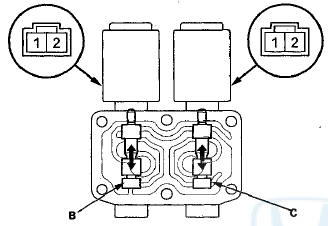
7. Disconnect the A/T clutch pressure control solenoid valve B and C connectors.
8. Measure the resistance between A/T clutch pressure control solenoid valve B or C connector terminals No. 1 and No. 2.
Standard: 3 - 1 0 
-If the resistance is within the standard, go to step 9.
-If the resistance is out of standard, replace A/T clutch pressure control solenoid valve B and C (see page 14-186).
9. Connect a jumper wire from the battery negative terminal to A/T clutch pressure control solenoid valve B or C connector terminal No. 2, and connect another jumper wire from the battery positive terminal to A/T clutch pressure control solenoid valve B or C connector terminal No. 1.
-If a clicking sound is heard, the valve is OK, and the test is complete, go to step 18.
-If no clicking sound is heard, go to step 10.
10. Remove A/T clutch pressure control solenoid valves B and C.
11. Remove the ATF joint pipes (A), the O-rings (D), and the gasket (E).
12. Check the fluid passage of A/T clutch pressure control solenoid valves B and C for contamination.
13. Connect a jumper wire from the battery negative terminal to A/T clutch pressure control solenoid valve B or C connector terminal No. 2, and connect another jumper wire from the battery positive terminal to connectorterminal No. 1. Make sure A/T clutch pressure control solenoid valve B or C moves.
14. Disconnect one of the jumper wires, and check the valve movement at the fluid passage in the valve body mounting surface. If the valve binds or moves sluggishly, or if the solenoid valve does not operate, replace A/T clutch pressure control solenoid valves B and C.
15. Clean the mounting surface and the fluid passage of the A/T clutch pressure control solenoid valve body and the transmission housing.
16. Install a new gasket on the transmission housing, and install the ATF joint pipes. Install new O-rings over the ATF joint pipes.
NOTE: Be sure to install a new gasket with the blue side toward the transmission housing.
17. Install A/T clutch pressure control solenoid valves B and C.
18. Check the connectors for rust, dirt, or oil, and clean or repair if necessary. Then connect the connectors securely.
19. Install the battery base (see step 63 on page 5-22).
20. Do the battery installation procedure (see page 22-92).
 A/T Clutch Pressure Control Solenoid
Valve A Replacement
A/T Clutch Pressure Control Solenoid
Valve A Replacement
1. Remove the intake air duct
2. Disconnect the A/T clutch pressure control solenoid
valve A connector.
3. Remove the bolts securing the ATF cooler line
brackets (B), then remove A/T clutch pres ...
 A/T Clutch Pressure Control Solenoid
Valve B and C Replacement
A/T Clutch Pressure Control Solenoid
Valve B and C Replacement
1. Do the battery removal procedure (see page 22-92).
2. Remove the battery base (see step 8 on page 5-3).
3. Disconnect the A/T clutch pressure control solenoid
valves B and C connectors.
4 ...
See also:
Secondary Shaft Disassembly,
Inspection, and Reassembly
1. Inspect the thrust needle bearings a n d the needle bearings for g a l l i
n g and rough movement
2. Inspect the splines for excessive wear and damage.
3. Check the shaft bearing surface fo ...
Wiper Motor Replacement
Removal
1. Open the hood. Remove the caps (A) and nuts (B).
NOTE: The illustration shows 4-door.
2. Close the hood, then spread protective cloths (A) on
the hood to avoid scratching the hood e ...
XM® Radio Service*
• Subscribing to XM® Radio
1. You need your radio ID ready before registering for subscription. To see
the ID in
the display: Turn the selector knob or the interface dial until 0 appears.
2. ...