 Honda Accord: Shift Lock System Circuit
Troubleshooting
1. Connect the HDS to the DLC (A) located under the driver's side of the dashboard.
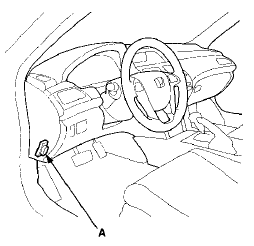
2. Turn the ignition switch to ON (II). Make sure the HDS communicates with the PCM. If it does not, go to the DLC circuit troubleshooting (see page 11-181).
3. Select Shift Lock Solenoid Test in the Miscellaneous Test Menu, and check that the shift lock solenoid operates with the HDS.
Does the shift lock solenoid work properly? YES
-Go to step 16.
NO
-Go to step 4.
4. Turn the ignition switch to LOCK (0).
5. Remove the shift lever assembly (see page 14-222).
6. Disconnect the shift lock solenoid connector (see page 14-254).
7. Turn the ignition switch to ON (II).
8. Measure the voltage between shift lock solenoid connector terminal No. 1 and body ground.
SHIFT LOCK SOLENOID CONNECTOR
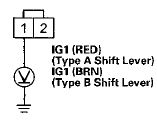
Wire side of female terminals
Is there battery voltage? YES
-Go to step 9.
NO
-Check for a blown No. 5 (7.5 A) fuse in the driver's under-dash fuse/relay box. If the fuse is OK, repair open in the wire between the shift lock solenoid connector and the driver's under-dash fuse/relay . - box.
9. Shift the shift lever to P, and press the brake pedal. Do not press the accelerator.
10. Measure the voltage between shift lock solenoid connector terminals No. 1 and No. 2 while pressing the brake pedal.
PHIFT LOCK SOLENOID CONNECTOR
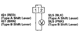
Wire side of female terminals
Is there battery voltage? YES
-Go to step 11.
NO
-Go to step 12.
11. Release the brake pedal, and measure the voltage between shift lock solenoid connector terminals No. 1 and No. 2. The shift lever must be in P.
SHIFT LOCK SOLENOID CONNECTOR
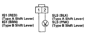
Wire side of female terminals
Is there battery voltage? YES
-Repair short to body ground in the wire between PCM connector terminal A28 and the shift lock solenoid.
NO
-Check the shift lock mechanism. If the mechanism is OK, replace the shift lock solenoid (see page14-254).
12. Turn the ignition switch to LOCK (0).
13. Jump the SCS line with the HDS.
14. Disconnect PCM connector A (49P).
15. Check for continuity between PCM connectorterminal A28 and shift lock solenoid connector terminal No. 2.
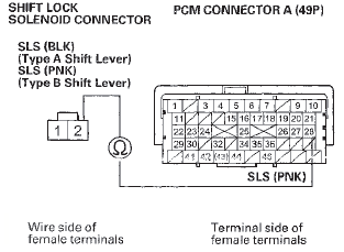
Is there continuity? YES
-Update the PCM if it does not have the latest software (see page 11-203), or substitute a known-good PCM (see page 11-7), then recheck. If the symptom goes away with a known-good PCM, replace the original PCM (see page 11-204).B NO-
Repair open in the wire between PCM connector terminal A28 and the shift lock solenoid connector.il 16. Monitor the Brake Switch in the Data List with the HDS, and press the brake pedal.
Is the Brake Switch ON? YES
-Go to step 22.
NO
-lf the brake lights come on, go to step 17. If the brake lights do not work, repair the faulty brake light circuit.
17. Turn the ignition switch to LOCK (0).
18. Jump the SCS line with the HDS.
19. Disconnect PCM connector A (49P).
20. Turn the ignition switch to ON (II).
21. Measure the voltage between PCM connector terminal A42 and body ground when pressing the brake pedal and when the brake pedal is released.
PCM CONNECTOR A (49P)
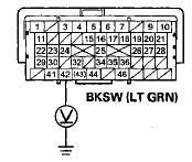
Terminal side of female terminals
Is there battery voltage when pressing the brake pedal, and about 0 V when the pedal is released? YES
-Update the PCM if it does not have the latest software (see page 11 -203), or substitute a known-good PCM (see page 11 -7), then recheck. If the symptom goes away with a known-good PCM, replace the original PCM (see page 11-204).
NO
-Repair open in the wire between PCM connector terminal A42 and the brake pedal position switch. 22. Monitor the A/T P Switch in the Data List with the HDS with the shift lever in P.
Is the A/T P Switch ON? YES
-Go to step 34.
NO
-Go to step 23.
23. Turn the ignition switch to LOCK (0).
24. Disconnect the transmission range switch connector.
25. Turn the ignition switch to ON (II).
26. Measure the voltage between transmission range switch connector terminals No. 6 and No. 10.
TRANSMISSION RANGE SWITCH CONNECTOR
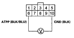
Wire side of female terminals
Is there battery voltage? YES
-Go to step 27.
NO
-Go to step 28.
27. Inspect the transmission range switch (see page 14-238).
Is the transmission range switch OK? YES
-Check for poor connections or loose terminals at the transmission range s w i t c h . NO-
Replace the transmission range switch (see page 14-240).
28. Turn the ignition switch to LOCK (0).
29. Jump the SCS line with the HDS.
30. Disconnect PCM connector B (49P).
31. Check for continuity between PCM connector terminal B14 and body ground.
PCM CONNECTOR B (49P)

Terminal side of female terminals
Is there continuity? YES
-Repair short to body ground in the wire between PCM connector terminal B14 and the transmission range switch connector.B NO
-Go to step 32.
32. Check for continuity between PCM connector terminal B14 and transmission range switch connector terminal No. 6.
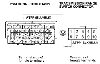
Is there continuity? YES
-Go to step 33.
NO-
Repair open in the wire between PCM connector terminal B14 and the transmission range switch connector.
33. Check for continuity between transmission range switch connector terminal No. 10 and body ground.
TRANSMISSION RANGE SWITCH CONNECTOR
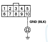
Wire side of female terminals
Is there continuity? YES
-Update the PCM if it does not have the latest software (see page 11 -203), or substitute a known-good PCM (see page 11-7), then recheck. If the symptom goes away with a known-good PCM, replace the original PCM (see page 11-204).
NO
-Repair open in the wire between transmission range switch connectorterminal No. 10 and body ground (G101), or repair poor ground (G101).
34. Check the APP Sensor A (Y) in the Data List with the HDS. Do not press the accelerator.
Is the APP sensor A opening 5 % and more, or 1.16 Vor higher? YES
-Check the APP Sensor (see page 11-239).
NO
-Update the PCM if it does not have the latest software (see page 11-203), or substitute a known-good PCM (see page 11-7), then recheck. If the symptom goes away with a known-good PCM, replace the original PCM (see page 11-204).
 Circuit Diagram
...
 Shift Lock Solenoid Test
1. Connect the HDS to the DLC (A) located under the
driver's side of the dashboard.
2. Turn the ignition switch to ON (II). Make sure the HDS
communicates with the PCM. If it does not, go to the
...
See also:
Clutch Pedal Assembly Replacement
1. Disconnect the clutch pedal position switch connector
(A) and the clutch interlock switch connector (B).
2. Pry out the lock pin (C), and pull the clevis pin (D) out
of the clevis.
3. Remov ...
Engine Block
...
Idler Gear/Idler Gear Shaft
Replacement
Special Tools Required
-Driver Handle, 15 x 135L 07749-0010000
-Attachment, 32 x 35 mm 07746-0010100
1. Remove the snap ring from the idler gear/idler shaft
assembly. Do not distort the snap ring. ...
