 Honda Accord: Secondary Shaft 1 st Gear Axial
Clearance Inspection
Special Tools Required
Attachment, 42 mm I.D. 07QAD-P0A0100 1. Remove the secondary shaft transmission housing bearing (see page 14-270).
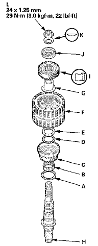
2. Install the thrust needle b e a r i n g (A), the needle bearing (B), 1st gear (C), the thrust needle bearing (D), the 40 x 51.5 mm thrust washer (E), the 1 st/3rd clutch (F), and the 3rd gear collar (G) on the secondary shaft (H). Do not install the O-rings during inspection.
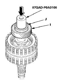
3. Install the idler gear (I), then install the transmission housing bearing (J) on the idler gear using the 42 mm I.D. attachment and a press.
4. Install the conical spring washer (K) and the locknut (L), then tighten the locknut to 29 N-m (3.0 kgfm, 22 Ibf-ft).
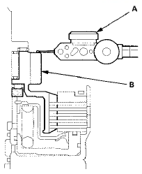
5. Turn the secondary shaft assembly upside down, and set a dial indicator (A) on 1st gear (B).
6. Lift 1st gear (A) up while holding the secondary shaft, and use the dial indicator (B) to read the 1 st gear axial clearance.
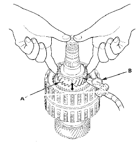
7. Measure the 1st gear axial clearance in at least three places while moving 1st gear. Use the average as the actual clearance.
Standard: 0.04-0.12 mm (0.002-0.005 in)
8. If the clearance is out of standard, remove the 40 x 51.5 mm thrust washer and measure its thickness.
9. Select and install a new thrust washer, then recheck.
THRUST WASHER, 40 x 51.5 mm
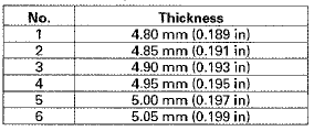
10. After replacing the thrust washer, make sure the clearance is within standard.
11. Disassemble the installed parts from the secondary shaft.
12. Reinstall the transmission housing bearing in the transmission housing (see page 14-271).
 Secondary Shaft 2nd Gear Axial
Clearance Inspection
1. Install the thrust needle bearing (A), the needle
bearing (B), 2nd gear (C), the thrust needle bearing
(D), the 37 x 58 mm thrust washer (E), and the 2nd
clutch (F) on the secondary shaft (G), t ...
 Idler Gear Shaft Removal and
Installation
1. Remove the snap ring (A), the cotter retainer (B), and
the 17 mm cotters (C). Do not distort the snap ring.
2. Remove the idler gear shaft/idler gear assembly (D)
from the transmission housing ...
See also:
Glove Box Striker Replacement
SRS components are located in this area. Review the
SRS component locations, 2-door {see page 24-23),
4-door (see page 24-21) and the precautions and
procedures (see page 24-25) before doing repair ...
Front Passenger's Weight Sensor Replacement
4-Door
Removal
NOTE;
• Removal of the front passenger's weight
sensors must
be done a c c o r d i n g to Precautions and Procedures (see
page 24-25).
•The front passenger' s weight ...
Rocker Arm Oil Pressure Switch B
Removal/Installation
PZEV model
1. Remove the rocker arm oil control valve (see page
11-275).
2. Remove rocker arm oil pressure switch B.
3. Install the parts in the reverse order of removal with a
new O-ring (A) ...
