 Honda Accord: Valve Seat Reconditioning
1. Inspect the valve stem-to-guide clearance (see page 6-88). If the valve guides are worn, replace them (see page 6-88) before cutting the valve seats.
2. Renew the valve seats in the cylinder head using a valve seat cutter.
3. Carefully cut a 45 Р’В° seat, removing only enough material to ensure a smooth and concentric seat.
4. Bevel the upper and lower edges at the angles shown in the illustration.Check the width of the seat and adjust accordingly.
5. Make one more very light pass with the 45 Р’В° cutter to remove any possible burrs caused by the other cutters.
Valve Seat Width
Standard (New): 1.25-1.55 mm (0.049-0.061 In)
Service Limit: 2.00 mm (0.079 in)
6. After resurfacing the seat, inspect for even valve seating. Apply Prussian Blue compound (A) to the valve face. Insert the valve in its original location in the head, then lift it and snap it closed against the seat several times.
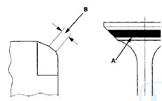
7. The actual valve seating surface (B), as shown by the blue compound, should be centered on the seat.
- If it is too high (closer to the valve stem), you must make a second cut with the 67.5 Р’В° cutter to move it down, then one more cut with the 45 Р’В° cutter to restore seat width.
- If it is too low (close to the valve edge), you must make a second cut with the 35 Р’В° cutter (intake side) or the 30 Р’В° cutter (exhaust side) to move it up, then make one more cut with the 45 Р’В° cutter to restore seat width.
NOTE: The final cut should always be made with the 45 Р’В° cutter.
8. Insert the intake and exhaust valves in the head, and measure the valve stem installed height (A).
Intake Valve Stem Installed Height
Standard (New): 44.0-44.5 mm (1.73-1.75 in)
Service Limit: 44.7 mm (1.76 in J
Exhaust Valve Stem Installed Height
Standard (New): 44.0-44.5 mm (1.73-1.75 in)
Service Limit: 44.7 mm (1.76 in)
9. If valve stem installed height is beyond the service limit, replace the valve and recheck. If it is still beyond the service limit, replace the cylinder head; the valve seat in the head is too deep.
 Waive Guide Replacement
Special Tools Required
Valve Guide Driver, 5.35 x 9.7 mm 07742-0010100
Valve Guide Reamer, 5.5 mm 07HAH-PJ7A100
1. Inspect the valve stem-to-guide clearance (see page
6-88).
2. As illustrated, ...
 Valve, Spring, and Valve Seal Installation
Special Tools Required
Stem Seal Driver, 30 mm 07PAD-0010000
Valve Spring Compressor Attachment 07757-PJ1010A
1. Coat the valve stems with new engine oil. Install the
valves in the valve guides.
...
See also:
Audio Remote Controls
Allows you to operate the audio system while driving.
The CD mode appears only when a CD is loaded.
...
Carrying Cargo in the Trunk
Distribute cargo evenly on the
floor of the trunk, placing the
heaviest items on the bottom and
as far forward as possible.
If you fold down the back seat, tie
down items that could be thrown ...
Component Location Index Rear Door
4-door
...