 Honda Accord: Stabilizer Link Removal/Installation
1. Raise and support the vehicle (see page 1 -13).
2. Remove the front wheel.
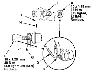
3. Remove the self-locking nut (A) and the flange nut (B) while holding the respective joint pin (C) with a hex wrench (D), then remove the stabilizer link (E).

4. Install the stabilizer link on the stabilizer bar (F) and * the lower arm (G) with the joint pins set at the center of their range of movement.
NOTE: The stabilizer link has a paint mark (H). The left stabilizer link is marked with yellow paint, and the right stabilizer link is marked with white paint.
5. Install the new self-locking nut and the new flange nut, and tighten them to the specified torque while holding the respective joint pin with a hex wrench.
6. Clean the mating surfaces of the brake disc and the inside of the wheel, then install the front wheel.
7. Test-drive the vehicle.
8. After 5 minutes of driving, tighten the self-locking nut again to the specified torque.
 Lower Arm Removal / Installation
Special Tools Required
- Ball Joint Thread Protector, 14 mm 07AAE-SJAA100
- Ball Joint Remover, 28 mm 07MAC-SL0A202
- Bushing Driver 070AF-TA0A100
- Bushing Receiver Set 070AF-TA0A220
Removal/Ins ...
 Stabilizer Bar Replacement
Special Tools Required
- Engine Hanger Adapter VSB02C000015*
- Engine Support Hanger, A and Reds AAR-T1256*
-Subframe Adapter VSB02C000016*
- Subframe Alignment Pin 070AG-SJAA10S
*: Available thr ...
See also:
Cruise Control
Cruise control allows you to maintain
a set speed above 25 mph (40 km/h)
without keeping your foot on the
accelerator pedal. It should be used
for cruising on straight, open
highways. It is ...
To Play a USB Flash Memory Device
This audio system can operate the
audio files on a USB flash memory
device with the same controls used
for the in-dash disc changer. To play
a USB flash memory device, connect
it to the USB ...
Instrument Panel
This chapter describes the buttons, indicators, and gauges that are used
while driving. ...
