 Honda Accord: Stabilizer Bar Replacement
Special Tools Required
- Engine Hanger Adapter VSB02C000015*
- Engine Support Hanger, A and Reds AAR-T1256*
-Subframe Adapter VSB02C000016*
- Subframe Alignment Pin 070AG-SJAA10S
*: Available through the Honda Tool and Equipment Program, 888-424-6857.
1. Note these items during replacement: - Be sure to remove the steering wheel before disconnecting the steering joint. Damage to the cable reel can occur.
- Lower the front subframe from the body, and replace the front stabilizer bar through the gap created by lowering the front subframe.
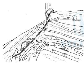
2. Remove the hood support rod, then use it as shown to prop the hood in the wide-open position.
3. Remove the front grille cover: - 4-door (see page 20-274) - 2-door (see page 20-274) 4. Do the battery terminal disconnection procedure (see page 22-91).
5. Raise and support the vehicle (see page 1-13).
6. Remove the front wheels.
7. Remove the driver's airbag and the steering wheel (see page 17-6).
8. Remove the steering joint cover (A).
9. Loosen the steering joint upper bolt (B), and remove the steering joint lower bolt (C). Disconnect the steering joint by sliding the steering joint into the column shaft (D). Tighten the steering joint upper bolt to hold the column shaft.
NOTE: - Do not disconnect the steering joint from the column shaft.
- If the center guide is in place and has not moved, leave it in place.
- If the center guide has moved or been removed, discard it.
10. Disconnect the power steering pressure (PSP) switch connector (A).
11. Remove the power steering pump outlet hose mounting bolt (A).
12. Remove the front strut brace (if equipped) (see page 20-306).
13. Attach the engine hanger adapter (VSB02C000015) to the threaded hole in the cylinder head.
14. Install the engine support hanger (AAR-T1256), then attach the hook to the slotted hole in the engine hanger adapter. Tighten the wing nut (A) by hand to lift and support the engine/transmission.
NOTE: Be careful when working around the windshield.
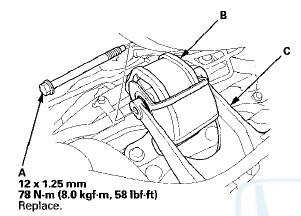
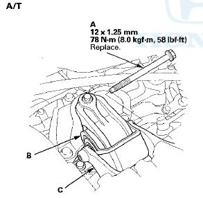
15. Remove the engine mount bolt (A) from the rear engine mount (B) and the rear engine mount bracket (C).
NOTE: Use a new engine mount bolt during reassembly.
M/T
16. Raise the vehicle on the lift to full height.
17. Remove the front splash shield (see page 20-291).
18. Remove the nuts (A) securing of the lower transmission mount.
19. Remove the exhaust pipe A hanger (A) from the front subframe.
20. Attach the subframe adapter (VSB02C000016) to the subframe, hang the belt of the subframe adapter over the front of the subframe, then secure the belt with its stop.
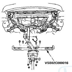
21. Raise the jack, line up the slots in the front subframe adapter arms with the bolt holes on the jack base, then securely attach them with four bolts.
22. Remove the front subframe mounting bolts (A) on both sides of the middle mount.
NOTE: Use new mounting bolts during reassembly.
23. Disconnect both sides of the stabilizer link from the stabilizer bar (see page 18-24).
24. Remove the flange bolts (A) on both sides of the front subframe front stiffener (B).
25. Loosen the front side of the subframe mounting bolts (C) to obtain a 20 mm (0.79 in) distance between the bolt seat and the mounting surface. Do not loosen the mounting bolts more than necessary.
26. Remove the flange bolts (A) on both sides of the front subframe rear stiffener (B).
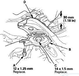
27. Loosen the rear side of the subframe mounting bolts (C) to obtain a 30 mm (1.18 in) distance between the bolt seat and the mounting surface. Do not loosen the mounting bolts more than necessary.
28. Lower the transmission jack with the front subframe adapter slowly until the front subframe (D) has dropped about 30 mm (1.18 in).
NOTE: Do not lower the front subframe beyond the loosened subframe mounting bolts clearance.
29. Remove the flange bolts (A) and the bushing holders (B), then remove the bushings (C).
NOTE: During installation, align the paint marks (D) on the stabilizer bar with the side of the bushings.
30. Move the stabilizer bar toward the passenger's side, and remove the stabilizer bar.
31. Install the stabilizer bar.
NOTE: - Note the right and left direction of the stabilizer bar.
- Note the direction of installation for the bushings.
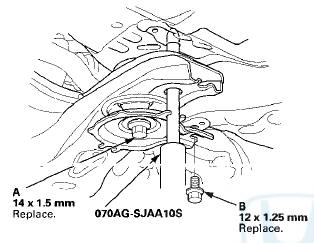
32. Align the front subframe using the subframe alignment pin. Vertically install the subframe alignment pin, and align the right-rear corner of the front subframe and vehicle frame holes, then loosely tighten the new subframe mounting bolt (A) until the front subframe contacts the body frame.
33. Loosely tighten the left-rear subframe mounting bolt using the same procedure as the right-rear with the subframe alignment pin.
34. Loosely install the new 12 mm flange bolts (B) to the subframe rear stiffener.
35. Torque the subframe mounting bolts to the specified torque starting with the right-rear bolt. Use the subframe alignment pin when tightening the rear side bolts (A).
NOTE: - Torque the bolts in the sequence shown.
- Before tightening the new front side subframe mounting bolts (B), raise the jack and loosely install the 12 mm flange bolts (C) to align the subframe front stiffener.
36. Check all of the front subframe mounting bolts, and retighten if necessary.
37. Install all of the removed parts In the reverse order of removal, and note these items; - Refer to stabilizer link removal/installation to connect the stabilizer bar to the links (see page 18-24).
- If the center guide is in place, use it to determine the steering joint installation angle.
- If the center guide is gone, check the steering joint installation angle (see step 3 on page 17-12).
- Check the steering wheel installation (see page 17-9).
- When connecting the rear engine mount to the rear engine mount bracket, first lightly tighten the mounting bolt, then remove the engine support hanger, and tighten it to the specified torque.
- Before installing the wheel, clean the mating surfaces of the brake disc and inside of the wheel.
38. Do the battery terminal reconnection procedure (see page 22-91), then turn the ignition switch to ON (ll) and check that the SRS indicator should come on for about 6 seconds and then go off.
39. Check the wheel alignment, and adjust it if necessary (see page 18-5).
 Stabilizer Link Removal/Installation
1. Raise and support the vehicle (see page 1 -13).
2. Remove the front wheel.
3. Remove the self-locking nut (A) and the flange nut (B)
while holding the respective joint pin (C) with a hex
wr ...
 Damper/Spring Removal and Installation
Removal
1. Raise and support the vehicle (see page 1-13).
2. Remove the front wheel.
3. Remove the wheel speed sensor harness bracket
mounting bolt (A).
4. Remove the damper pinch b ...
See also:
Audio Switch Panel
Removal/Installation
With Navigation
NOTE:
• Put on gloves to protect your hands.
• Take care not to scratch the dashboard and related
parts.
• Lay a workshop towel under the parts when working
on ...
Transmission Fluid Pressure Switch A
(2nd Clutch) Replacement
1. Remove the intake air duct.
2. Disconnect the connector (A) from the transmission
fluid pressure switch A (2nd clutch) (B), and remove
the transmission fluid pressure switch A (2nd clutch).
...
System Description
HandsFreeLink Control Unit Inputs and Outputs
HandsFreeLink Control Unit 28P Connector
*l:The shielded wires have a heat-shrink tube insulating the outside of the
wire. The color of the insula ...