 Honda Accord: Lower Arm Removal / Installation
Special Tools Required
- Ball Joint Thread Protector, 14 mm 07AAE-SJAA100
- Ball Joint Remover, 28 mm 07MAC-SL0A202
- Bushing Driver 070AF-TA0A100
- Bushing Receiver Set 070AF-TA0A220
Removal/Installation
1. Raise and support the vehicle (see page 1-13).
2. Remove the front wheel.
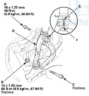
3. Remove the damper pinch bolt (A) and the damper fork mounting nut (B) while holding the mounting bolt (C), then remove the damper fork (D) from the damper and the lower arm.
NOTE: - During installation, insert the aligning tab (E) on the damper unit into the slot (F) of the damper fork.
- Use the new damper fork mounting bolt and the new mounting nut, and torque the nut while holding the bolt during reassembly.
4. Disconnect the stabilizer link from the lower arm (see page 18-24).
5. Remove the cotter pin (A) from the knuckle ball joint, then remove the castle nut (B).
NOTE: During installation, insert the new cotter pin into the ball joint pin hole from the front to the rear of the vehicle, and bend its end as shown. Check the ball joint pin hole direction before connecting the ball joint.
6. Disconnect the knuckle ball joint from the lower arm using the ball joint thread protector and the ball joint remover (see page 18-10).
NOTE: - Be careful not to damage the ball joint boot when installing the remover.
- Do not force or hammer on the lower arm, or pry between the lower arm and the knuckle. You could damage the ball joint.
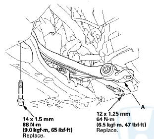
7. Remove the lower arm mounting bolts, and remove the lower arm (A).
NOTE: Use new lower arm mounting bolts during reassembly.
8. Install the lower arm in the reverse order of removal, and note these items: - First install all of the components, and lightly tighten the bolts and the nuts, then raise the suspension to load it with the vehicle's weight before fully tightening it to the specified torque. Do not place the jack against the ball joint pin of the knuckle.
- Be careful not to damage the ball joint boot when connecting the knuckle.
- Before connecting the ball joint, degrease the threaded section and the tapered portion of the ball joint pin, the ball joint connecting hole, and the threaded section and the mating surfaces of the castle nut.
- Torque the castle nut to the lower torque specification then tighton it only for onough to align the slot with the ball joint pin hole. Do not align the castle nut by loosening it.
- Before installing the wheel, clean the mating surfaces of the brake disc and the inside of the wheel.
9. Check the wheel alignment, and adjust it if necessary (see page 18-5).
Compliance Bushing Replacement
1 . Remove the lower arm.
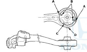
2. Mark alignment marks (A) on the bottom of the lower arm next to the aligning marks (B) on the compliance bushing.
NOTE: The compliance bushing has a specific installation position. Turn the lower arm so that its bottom side is up. Position the bushing identifying mark (C) face up and near the tab (D) on the lower arm. Then align the bushing aligning marks on the bushing and the lower arm.
If the alignment marks are gone, align the angle (E) between the lower arm and the bushing as shown.
Aligning the marking position
Aligning the angle (reference)
3. Press out the compliance bushing (A) with the bushing driver, the bushing receiver set (attachment A), and a hydraulic press, and remove the bushing from the lower arm (B).
NOTE: Be careful not to damage the inside of the bushing hole on the lower arm.
4. Clean the mating surfaces of the new compliance bushing (A) and the lower arm (B).
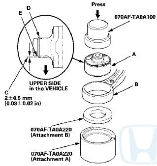
5. Make sure of the compliance bushing installation direction, align the bushing aligning marks with the lower arm, then press in the bushing into the lower arm using the bushing driver, the bushing receiver set (attachments A and B), and a hydraulic press.
NOTE; - Press In the bushing from the bottom side of the lower arm.
- After installation, check the protrusion (C) of the bushing outer sleeve (D) through the lower arm bushing hole (E).
6. Install the lower arm.
 Upper Arm Replacement
Special Tools Required
-Ball Joint Thread Protector, 10 mm
07AAF-SECA120
- Ball Joint Remover, 28 mm 07MAC-SL0A202
1. Raise and support the vehicle (see page 1-13).
2. Remove the front wheel.
...
 Stabilizer Link Removal/Installation
1. Raise and support the vehicle (see page 1 -13).
2. Remove the front wheel.
3. Remove the self-locking nut (A) and the flange nut (B)
while holding the respective joint pin (C) with a hex
wr ...
See also:
Component Location Index
2-door
4-door
...
Shift Lever Installation
1. Install the shift lever assembly (A).
Type A Shift Lever
Type B Shift Lever
2. Connect the shift lock solenoid connector (B) and the
park pin switch/A/T gear position indicator panel light
...