 Honda Accord: Tire Pressure Sensor Replacement
Removal

Each tire pressure sensor contains a lithium anode battery that is not removable. The complete tire pressure sensor should be disposed of according to local battery disposal guidelines or requirements. An improperly disposed of battery can be harmful to the environment.
1. Raise and support the vehicle (see page 1-13).
2. Remove the wheel with the faulty sensor.
3. Remove the tire valve stem cap and the valve stem core to deflate the tire.
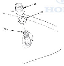
4. Remove any balance weights, and then break the bead loose from the wheel with a commercially available tire changer ( A ).

Note these items to avoid damaging the tire pressure sensor: - Do the outside of the wheel first.
- Position the wheel as shown so the valve stem (B) is 90 degrees from the bead breaker (C) as shown.
- Do not position the bead breaker of the tire changer too close to the rim.
5. Position the wheel so that the tire machine (A) and the tire iron (B) are next to the valve stem (C), and will move away from it when the machine starts. Then remove the tire from the wheel.
6. Remove the valve stem nut (A) and the washer (B), then remove the tire pressure sensor with the valve stem (C) from the wheel.
NOTE: Check the nut and the washer; if they have deterioration or damage, replace them with new ones during reassembly.
7. Remove and discard the valve stem grommet (A) from the tire pressure sensor (B).
NOTE: - The valve stem grommet might stay in the wheel; make sure you remove it.
- Always use a new valve stem grommet whenever the tire pressure sensor has been removed from the wheel, or when replacing the tire.
installation
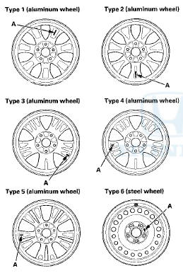
NOTE: - Use only wheels that have a "TPMS", "TA0", or "TEO" stamp (A) on the inside of the aluminum wheels, and the outside of the steel wheels.
- The vehicle may be equipped with one of the six types of wheels.
1. Before installing the tire pressure sensor, clean the mating surfaces on the sensor and the wheel.
2. Install the tire pressure sensor (A) and the washer (B) to the wheel (C), and tighten the valve stem nut (D) finger tight. Make sure the pressure sensor is resting on the wheel.
NOTE: Install the tire pressure sensor so that the sensor housing surface (E) should not exceed the protrusion (F) of the wheel to prevent the sensor housing from being caught on the bead of the tire when assembling the tire. Be sure to always mount the tire pressure sensor with the feet (G) in the downward position toward the wheel.
3. Tighten the valve stem nut to the specified torque while holding the tire pressure sensor.
NOTE: - Do not use air or electric impact tools to tighten a valve stem nut.
- Do not twist the tire pressure sensor to adjust its position with the wheel, as this will damage or deform the valve stem grommet.
4. Lube the tire bead sparingly with a paste-type tire mounting lubricant, and position the wheel so that the tire machine (A) is next to the valve stem (B) and will move away from it when the machine starts. Then install the tire onto the wheel.
5. With a dry air source, inflate the tire to 300 kPa (3.1 kgf/cm2,44 psi) to seat the tire bead to the rim, then adjust the tire pressure (see page 18-5), and install the valve stem cap.
NOTE: Make sure the tire bead is seated on both sides of the rim evenly.
6. Check and adjust the wheel balance, then install the wheels on the vehicle.
7. Lower the vehicle. Torque the wheel nuts to specifications (see step 2 on page 18-14).
8. Connect the HDS, and memorize the pressure sensor IDs using the TPMS tool (see page 18-60).
SUPPLEMENTAL RESTRAINT SYSTEM (SRS) (if brakes maintenance is required)
The Accord SRS includes a driver's airbag in the steering wheel hub, a passenger's airbag in the dashboard above the glove box, seat belt tensioners in the front seat belt retractors, side curtain airbags in the sides of the roof, and side airbags in the front seat-backs. Information necessary to safely service the SRS is included in this Service Manual. Items marked with an asterisk (*) on the contents page include or are located near SRS components. Servicing, disassembling, or replacing these items requires special precautions and tools, and should be done by an authorized Honda dealer.
- To avoid rendering the SRS inoperative, which could lead to personal injury or death in the event of a severe frontal or side collision, all SRS service work should be done by an authorized Honda dealer.
- Improper service procedures, including incorrect removal and installation of the SRS, could lead to personal injury caused by unintentional deployment of the airbags, side airbags, and/or side curtain airbags.
- Do not bump or impact the SRS unit, front impact sensors, side impact sensors, or rear safing sensor, especially when the ignition switch is in ON (II), or for at least 3 minutes after the ignition switch is turned to LOCK (0); otherwise, the system may fail in a collision, or the airbags may deploy.
- SRS electrical connectors are identified by yellow color coding. Related components are located in the steering column, center console, dashboard, dashboard lower cover, in the dashboard above the glove box, in the front seats, in the roof side, and around the floor. Do not use electrical test equipment on these circuits.
 TPMS Control Unit Replacement
NOTE: Make sure the TPMS control unit mounting
bracket is not bent or twisted as this may affect its
communication with the tire pressure sensors.
1. Turn the ignition switch to LOCK (0).
2. R ...
 Brakes
...
See also:
Additional Safety Precautions
Do not let a child wear a seat belt
across the neck. This could result
in serious neck injuries during a
crash.
Do not let a child put the shoulder
part of a seat belt behind the back
or un ...
Special Tools
...
Blower Unit Removal/Installation
1. Remove the glove box (see page 20-174).
2. Remove the passenger's undercover (see page
20-170).
3. Remove the right kick panel (see page 20-107).
4. Remove the dust and pollen filter asse ...