 Honda Accord: Shift Solenoid Valve Test,
Replacement, and Shift Solenoid
Wire Harness Replacement
Honda Accord: Shift Solenoid Valve Test,
Replacement, and Shift Solenoid
Wire Harness Replacement
1. Connect the HDS to the DLC (A) located under the driver's side of the dashboard.
2. Turn the ignition switch to ON (II). Make sure the HDS communicates with the PCM. If it does not go to the DLC circuit troubleshooting (see page 11-181).
3. Select Shift Solenoid Valves A, B, C, D, or E in the Miscellaneous Test Menu on the HDS.
4. Check that shift solenoid valves A, B, C, D, or E operate with the HDS. A clicking sound should be heard.
-If a clicking sound is heard, the valves are OK. The test is complete, disconnect the HDS.
-If no clicking sound is heard, go to step 5.
5. Raise the vehicle on a lift, or apply the parking brake, block both rear wheels, and raise the front of the vehicle. Make sure it is securely supported.
6. Remove the splash shield.
7. Disconnect the shift solenoid wire harness connector.
Terminal side of male terminals
8. Measure the resistance between each of the following terminals and body ground:
-No. 1 terminal: Shift solenoid valve C
-No. 2. terminal: Shift solenoid valve B
-No. 3 terminal: Shift solenoid valve E
-No. 5 terminal: Shift solenoid valve A
-No. 8 terminal: Shift solenoid valve D
Standard: 1 2 - 2 5 0
-If the resistance is within the standard, go to step 9.
-If the resistance is out of standard, go to step 10.
9. Connect a jumper wire from the battery positive terminal to each shift solenoid wire harness connector terminal individually. A clicking sound should be heard.
-If a clicking sound is heard, the valves are OK. The test is complete, reconnect the connector, then install the splash shield.
-If no clicking sound is heard, go to step 10.
10. Remove the drain plug (A), and drain the ATF.
11. Reinstall the drain plug with a new sealing washer (B).
12. Remove the left front wheel.
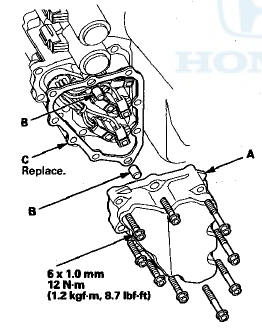
13. Remove the shift solenoid valve cover (A), the dowel pins (B), and the gasket (C).
14. Disconnect the shift solenoid valve connectors from the shift solenoid valve(s) that did not click.
15. Measure the resistance of each shift solenoid valve between the connector terminals and body ground:
Standard: 1 2 - 2 5

-If the resistance is within the standard, go to step 16.
-If the resistance is out of standard, go to step 18.
16. Connect a jumper wire from the battery positive terminal to each shift solenoid valve connector terminal individually. A clicking sound should be heard.
-If a clicking sound is heard, go to step 17.
-If no clicking sound is heard, go to step 18.
17. Remove the bolt securing the shift solenoid wire harness (A), replace the shift solenoid wire harness and the O-ring (B), then go to step 23.
18. Remove the shift solenoid valve mounting bolts (F), then hold the shift solenoid valve body, and remove the affected shift solenoid valves.
NOTE: Do not hold the shift solenoid valve connector to remove the shift solenoid valves. Be sure to hold the shift solenoid valve body.

19. Install new O-rings (two O-rings per shift solenoid valve) (G) on the shift solenoid valves.
NOTE: A new shift solenoid valve comes with new O-rings. If you install a new shift solenoid valve, use the O-rings provided with it.
20. If shift solenoid valve C, D, or E was replaced, install shift solenoid valve C (brown connector), shift solenoid valve D (black connector), or shift solenoid valve E (black connector) by holding the shift solenoid valve body; make sure the mounting bracket contacts the servo body. , NOTE: Do not hold the shift solenoid valve connector to install the shift solenoid valve. Be sure to hold the shift solenoid valve body.
21. If shift solenoid valve A was replaced, install shift solenoid valve A (brown connector) by holding the shift solenoid valve body; make sure the mounting bracket contacts the bracket of shift solenoid valve D.
NOTE: Do not install shift solenoid valve A before installing shift solenoid valve D. If shift solenoid valve A is installed before installing shift solenoid valve D, it may damage the hydraulic control system.
22. If shift solenoid valve B was replaced, install shift solenoid valve B (brown connector) by holding the shift solenoid valve body; make sure the mounting bracket contacts the bracket of shift solenoid valve E.
NOTE: Do not install shift solenoid valve B before installing shift solenoid valve E. If shift solenoid valve B is installed before installing shift solenoid valve E, it may damage the hydraulic control system.
23. Connect the shift solenoid valve connectors:
-RED wire connector to shift solenoid valve E.
-GRN wire connector to shift solenoid valve C.
-ORN wire connector to shift solenoid valve B.
-BLU wire connector to shift solenoid valve A.
-YEL, WHT, and WHT wire connector to shift
solenoid valve D.
24. Install a new gasket, the dowel pins, and the shift solenoid valve cover.
25. Check the connector for rust, dirt, or oil, and clean or repair if necessary, then connector the connector securely.
26. Refill the transmission with ATF (see step 4 on page 14-192).
27. Install the splash shield.
28. Install the left front wheel.
 Pressure Test
Special Tools Required
•A/T Oil Pressure Gauge Set 07406-0020400
or
07406-0020401
•A/T Pressure Hose, 2,210 mm
07MAJ-PY4011A
•A/T Pressure Adapter 07MAJ-PY40120
NOTE:
-Disable ...
 A/T Clutch Pressure Control Solenoid
Valve A Test
A/T Clutch Pressure Control Solenoid
Valve A Test
1. Connect the HDS to the DLC (A) located under the
driver's side of the dashboard.
2. Turn the ignition switch to ON (II). Make sure the HDS
communicates with the PCM. If it does not, go to the
...
See also:
Stabilizer Link Removal/Installation
1. Raise and support the vehicle (see page 1 -13).
2. Remove the rear wheel.
3. Remove the flange nut (A) and the self-locking nut (B)
while holding the respective joint pin (C) with a hex
wre ...
To Play the Radio
The band and frequency that the
radio was last tuned to are displayed.
To change bands, press the AM or
FM button. On the FM band, ST will
be displayed if the station is
broadcasting in stere ...
Setting the Clock
Clock
You can adjust the time in the clock display with the ignition switch is in
ON
The clock is automatically updated through the
navigation system, so the time does not need to be
adju ...