 Honda Accord: Rocker Arm Assemblf Installation
1. Reassemble the rocker arm assembly (see page 6-82).
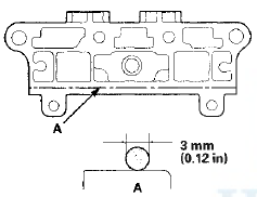
2. Clean and dry the No. 5 rocker shaft holder mating surface.
3. Apply liquid gasket P/N 08717-0004, 08718-0003, or 08718-0009 to the cylinder head mating surface of the No. 5 rocker shaft holder, and to the inside edge of the threaded bolt holes. Install the component within 5 minutes of applying the liquid gasket.
NOTE: - Apply a 3 mm (0.12 in) diameter bead of liquid gasket along the broken line (A).
- If too much time has passed after applying the liquid gasket, remove the old liquid gasket and residue, then reapply new liquid gasket.
4. Install the lost motion assembly in the cylinder head.
5. Insert the bolts (A) into the rocker shaft holder, then install the rocker arm assembly (B) on the cylinder head.
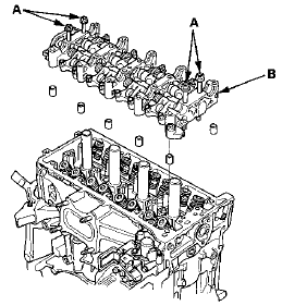
6. Remove the bolts from the rocker shaft holder.
7. Make sure the punch marks on the variable valve timing control (VTC) actuator and the exhaust camshaft sprocket are facing up, then set the camshafts (A) in the holder. Apply new engine oil to the camshaft journals and lobes.
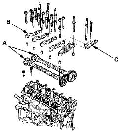
8. Set the camshaft holders (B) and cam chain guide B (C) in place.
9. Tighten the bolts to the specified torque.
NOTE: If the engine does not have bolt 
, skip it and
continue the torque sequence.
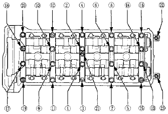
Specified Torque
8x1.25 mm 22 N-m (2.2 kgf-m, 16 Ibfft)
6x1.0 mm 12 N-m (1.2 kgf-m, 8.7 Ibfft)
6x1.0 mm Bolts:  ,
, ,
,
10. Install the cam chain (see page 6-64), then adjust the valve clearance (see page 6-58).
 Valve, Spring, and Valve Seal Installation
Special Tools Required
Stem Seal Driver, 30 mm 07PAD-0010000
Valve Spring Compressor Attachment 07757-PJ1010A
1. Coat the valve stems with new engine oil. Install the
valves in the valve guides.
...
 Cylinder Head Installation
1. Install a new coolant separator (A) In the engine block
whenever the engine block is replaced.
2. Clean the cylinder head and the engine block surface.
3. Install the new cylinder head gaske ...
See also:
Precautions for Opening/Closing the Trunk
• Opening the trunk
Open the trunk all the way.
- If it is not fully opened, the trunk lid may begin to close under its own
weight.
• Closing the trunk
Keep the trunk lid closed while ...
Setting the Clock
Clock
You can adjust the time in the clock display with the ignition switch is in
ON
The clock is automatically updated through the
navigation system, so the time does not need to be
adju ...
Air Cleaner Removal/Installation
1. Disconnect the MAF sensor/IAT sensor connector (A).
2. Remove the harness clamps (B) and the bolts (C).
3. Loosen the band (D), then remove the air cleaner
housing (E).
4. Install the par ...