 Honda Accord: ODS Unit Replacement
Removal
1. Do t h e battery t e r m i n a l disconnection procedure (see page 22-91), t h e n w a i t at least 3 minutes before s t a r t i ng work.
2. Remove t h e f r o n t passenger's seat (see page 20-194).
3. T u r n over t h e seat-back cover/pad as needed: • 4-door (see page 20-221) • 2-door (see page 20-213) 4. Remove t h e cover (A), t h e n disconnect t h e ODS unit 18P connector (B) a n d OPDS sensor connectors (C) from t h e ODS unit (D).
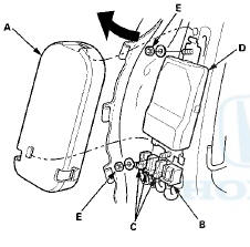
5. Remove t h e t w o washers, nuts (E), a n d t h e ODS unit.
Installation
1. Place t h e ODS unit (A) o n t h e seat-back f r a m e . Install t h e t w o washers and nuts, a n d t o r q u e t h e t w o nuts (B) , t h e n connect t h e ODS unit harness 18P connector (C) and OPDS sensor connectors (D) t o t h e ODS unit.
Reinstall t h e cover (E).
2. Install t h e seat-back cover cover/pad in t h e reverse order of removal: • 4-door (see page 20-221) • 2-door (see page 20-213) 3. Install t h e f r o n t passenger's seat (see page 20-200).
4. Do t h e battery t e r m i n a l reconnection procedure (see page 22-91).
5. Clear any DTCs w i t h t h e HDS (see page 24-38).
6. Set t he seat-back in t h e normal p o s i t i o n , a n d make sure t h e r e is n o t h i n g o n t h e f r o n t passenger's seat.
7 Do t he ODS unit i n i t i a l i z a t i on (see page 24-40).
8. C o n f i rm proper SRS operation: T u r n t he i g n i t i on s w i t c h t o ON (II); t h e SRS indicator should come on f o r about 6 seconds and t h e n g o off.
 Front Passenger's Weight Sensor Replacement
4-Door
Removal
NOTE;
• Removal of the front passenger's weight
sensors must
be done a c c o r d i n g to Precautions and Procedures (see
page 24-25).
•The front passenger' s weight ...
 Front Impact Sensor Replacement
Removal
1. Do t h e battery t e r m i n a l d i s c o n n e c t i o n procedure (see
page 22-91), t h e n w a i t at least 3 m i n u t e s before
s t a r t i ng work.
2. Remove t h e f r o n t b ...
See also:
Fuel Pressure Regulator Replacement
1. Remove the fuel tank unit (see page 11-320).
2. Remove the reservoir (A).
3. Remove the bracket (B).
4. Remove the fuel pressure regulator (C).
5. Install the parts in the reverse order ...
Engine Coolant
Adding Engine Coolant
If the coolant level in the reserve
tank is at or below the MIN line, add
coolant to bring it up to the MAX line.
Inspect the cooling system for leaks.
Always use Hond ...
Charging the Battery
Disconnect both battery cables to prevent damaging your vehicle's electrical
system.
Always disconnect the negative (–) cable first, and reconnect it last. ...