 Honda Accord: General Troubleshooting Information
Troubleshooting CAN Circuit Related Problems
NOTE: If you are troubleshooting multiple DTCs, be sure to follow the instructions in B-Can System Diagnosis Test Mode A (see page 22-134)..
Using the HDS (Preferred method)
Connect the HDS to the Data Link Connector (DLC).
There are two ways to read B-CAN code with the HDS: • First method; Go to B-CAN System Diagnosis Test Mode A to check for DTCs (see page 22-134).
• Second method; Ground the SCS circuit with the HDS, then reed the DTCs displayed in the odo/trip display in t h e gauge assembly, then go to B-CAN System Diagnosis Test Mode A (see page 22-134).
Using the B-CAN System Diagnosis Test Mode 1 (Use only if the HDS is unavailable)
1. Check for communication circuit problems using B-CAN System Diagnostic Test Mode 1 (see page 22-138).
2. Check for DTCs.
3. If multiple DTCs are stored, sort them, and then troubleshoot the DTCs in this order:
-1. Battery voltage DTCs
-2. Internal error DTCs
-3. Loss of communication DTCs
NOTE: If DTC U1280 is stored, troubleshoot DTC U1280 (see page 22-148) first.
-4. Signal error DTCs
4. If no DTCs are retrieved, use B-CAN System Diagnostic Test Mode 2 to check all inputs related to the failure (see page 22-138).
How to display DTCs on the gauge control module
Enter B-CAN System Diagnosis Test Mode 1 (see page 22-138). While in Test Mode 1 when communication between the MICU and gauge control module is normal the DTCs which have been detected and stored individually by various B-CAN (Body-controller Area Network) unit, will be shown one by one on the LCD display. To scroll through the DTCs, press the SEL/RESET button.
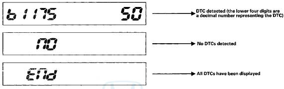
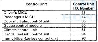
The control unit that has stored the code can be identified by the number shown on the odometer display.
How to ciear the DTC
Enter B-CAN System Diagnosis Test Mode 1 (see page 22-138). While in Test Mode 1, press and hold down the SEL/RESET button for at least 10 seconds.
Loss of Communication DTC cross-reference chart
When an ECU on the CAN circuit is unable to communicate with other ECUs on the CAN circuit, the other control units will set loss of communication DTCs. Use this chart to find the control unit that is not communicating with the other control units on the CAN circuit.
1. Find the Transmitting Control Unit that is in the same row as all of the loss of communication DTCs retrieved.
2. Do the input test for the transmitting control unit.
BUS OFF and Internal Error Codes
Loss of Communication
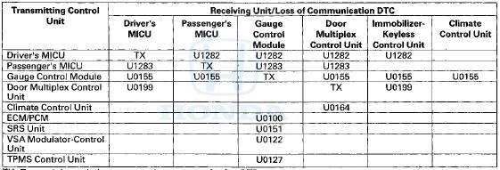
TX: Transmitting unit does not set a loss communication DTC.

 DTC Troubleshooting Index
NOTE: Record all DTCs, and sort them by DTC type using the DTC
troubleshooting index, then troubleshoot the DTC(s)
in this order:
• Battery voltage DTCs
• Internal error DTCs
• Lo ...
See also:
Wiper Arm/Nozzle Adjustment
4-door
1. Turn the wiper switch ON, and then back OFF.
2. W h e n t h e w i p e r a r m s s t o p at t h e p a r k p o s i t i o n , c
o n f i rm that t h e y a r e at t h e s t a n d a r d posi ...
Compass Zone Selection
In most areas, there is a variation
between magnetic north and true
north. Zone selection is required so
the compass can compensate for this
variation. To check and select the
zone, do this: ...
Playing Discs (Models without navigation system)
Playing Discs (Models without navigation system) ...