 Honda Accord: Front Passenger's Weight Sensor Replacement
4-Door
Removal
NOTE; • Removal of the front passenger's weight sensors must be done a c c o r d i n g to Precautions and Procedures (see page 24-25).
•The front passenger' s weight sensors are part of the seat frame and must be replaced the front passenger's seat frame assembly.
1. Do t h e b a t t e r y t e r m i n a l disconnection procedure (see page 22-91), then wait at least 3 m i n u t e s before s t a r t i ng work.
2. Remove t h e f r o n t passenger's seat f r a m e / f r o nt passenger's w e i g h t sensor as t h e f r o n t passenger's seat f r a m e assembly (see page 20-208).
Installation
NOTE: • Be s u r e t o install t h e harness w i r e s so t h e y are n o t pinched o r i n t e r f e r i n g w i t h other parts.
• The f r o n t passenger's w e i g h t sensor are p a r t of t h e seat f r a m e and m u s t be replaced as t h e f r o n t passenger's seat f r a m e assembly.
1. Install t h e r e m o v e d parts t o t h e n e w seat f r a m e / f r o nt passenger's w e i g h t sensor as t h e f r o n t passenger's seat f r a m e assembly.
2. Do t h e b a t t e r y t e r m i n a l reconnection procedure (see page 22-91).
3. Clear a n y DTCs w i t h t h e HDS (see page 24-38).
4. Do t h e f r o n t passenger's w e i g h t sensor i n i t i a l i z a t i on (see page 24-40).
5. C o n f i rm proper SRS o p e r a t i o n : T u r n t h e i g n i t i on s w i t c h t o O N (II); t h e SRS indicator s h o u l d c o m e on f o r about 6 seconds and t h e n g o off.
2-Door
Removal
NOTE: • Removal of the front passenger's weight sensors must be done according to Precautions and Procedures (see page 24-25).
• The front passenger's weight sensor are part of the seat rail and must be replaced as the front passenger's seat frame assembly.
1. Do the battery terminal disconnection procedure (see page 22-91), then wait at least 3 minutes before starting work.
2. Remove the front passenger's seat (see page 20-194).
3. Remove t h e upper rail o u t e r cover a n d upper rail inner cover (see page 20-211).
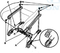
4. Disconnect the front passenger's weight sensor connectors (A) from the ODS unit harness. Remove the mounting TORX bolts (B) from front passenger's weight sensors (C), then remove it.
Installation
NOTE: • Be sure to install the harness wires so they are not pinched or interfere with other parts.
• Make sure both of the hooks (A) on the seat track are properly secured to the front bracket (B). If the hooks are not properly secured, the front passenger's weight sensors will not perform properly.
1. Install and torque the front passenger's weight sensors with new mounting TORX bolts (C) under the seat cushion.
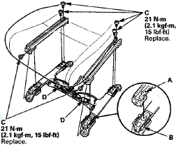
2. Connect the front passenger's weight sensor connectors (D) to the ODS unit harness.
3. Install the upper rail outer cover and upper rail inner cover (see page 20-211).
4. Install the front passenger's seat (see page 20-194).
5. Do the battery terminal reconnection procedure (see page 22-91).
6. Clear any DTCs with the HDS (see page 24-38).
7. Do the front passenger's weight sensor initialization (see page 24-40).
8. Confirm proper SRS operation: Turn the ignition switch to ON (II); the SRS indicator should come on for about 6 seconds and then go off.
 Rear Safing Sensor Replacement
Removal
1. Do the battery t e r m i n a l disconnection p r o c e d u r e (see
page 22-91), t h e n wait at least 3 minutes before
starting w o r k .
2. Remove t h e rear seat c u s h i o n (see ...
 ODS Unit Replacement
Removal
1. Do t h e battery t e r m i n a l disconnection procedure (see
page 22-91), t h e n w a i t at least 3 minutes before
s t a r t i ng work.
2. Remove t h e f r o n t passenger's seat (s ...
See also:
Important Safety Precautions
• Always wear your seat belt
A seat belt is your best protection in all types of collisions. Airbags are
designed to
supplement seat belts, not replace them. So even though your vehicle is equi ...
Synchro Sleeve and Hub Inspection and
Reassembly
1. Inspect the gear teeth on all synchro hubs and
synchro sleeves for wear (rounded off corners).
2. Install each synchro hub (A) in its mating synchro
sleeve (B), and check for free movement. Ma ...
Replacing a Front Side Marker Light Bulb
1. To change the bulb on the driver’s
side, start the engine, turn the
steering wheel all the way to the
right, then turn off the engine. To
change the bulb on the passenger’s
side, tu ...