 Honda Accord: Rear Safing Sensor Replacement
Removal
1. Do the battery t e r m i n a l disconnection p r o c e d u r e (see page 22-91), t h e n wait at least 3 minutes before starting w o r k .
2. Remove t h e rear seat c u s h i o n (see p a g e 20-241).
3. Disconnect t h e SRS f l o o r w i r e harness 2P (4-door) or 4P (2-door) connector (A) f r om t h e rear s a f i n g sensor (B).
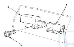
4. Remove t h e TORX b o l t (C) u s i n g a TORX T30 b i t t h en remove t h e rear s a f i n g sensor.
Installation
1. Install t h e rear s a f i n g sensor (A) w i t h a n e w TORX bolt (B), u s i n g a TORX T30 b i t . Connect t h e SRS f l o o r w i re harness 2P (4-door) o r 4P (2-door) connector (C) t o t h e rear s a f i n g sensor.
2. D o t h e b a t t e r y t e r m i n a l reconnection procedure (see page 22-91).
3. Clear a n y DTCs w i t h t h e HDS (see p a g e 24-38).
4. C o n f i rm proper SRS o p e r a t i o n : T u r n t h e i g n i t i on s w i t c h t o O N (II); t h e SRS i n d i c a t o r s h o u l d c o m e on f o r about 6 seconds and t h e n g o off.
5. Reinstall all r e m o v e d parts.
 Side Impact Sensor (Second) Replacement
4-Door
Removal
1. Do t h e b a t t e r y t e r m i n a l d i s c o n n e c t i o n procedure
(see
page 22-91), t h e n w a i t at least 3 m i n u t e s before
s t a r t i ng work.
2. Remove t ...
 Front Passenger's Weight Sensor Replacement
4-Door
Removal
NOTE;
• Removal of the front passenger's weight
sensors must
be done a c c o r d i n g to Precautions and Procedures (see
page 24-25).
•The front passenger' s weight ...
See also:
Climate Control Unit
Removal / Installation
With Navigation
1. Remove the passenger's dashboard undercover (see
page 20-170).
2. Disconnect the connectors (A). Loosen the bolt (B)
and remove the bolts (C) from the climate control unit (D) ...
Idler Gear Shaft Removal and
Installation
1. Remove the snap ring (A), the cotter retainer (B), and
the 17 mm cotters (C). Do not distort the snap ring.
2. Remove the idler gear shaft/idler gear assembly (D)
from the transmission housing ...
A/T Gear Position Indicator Panel Light
Harness Replacement
Type A Shift Lever
NOTE: The A/T gear position indicator panel light
harness and the park pin switch are not available
separately. Replace the A/T gear position indicator panel
light harness and t ...