 Honda Accord: Lower Arm B Replacement
1 Raise and support the vehicle (see page 1-13).
2. Remove the rear wheel.
3. Remove the lower arm B mounting bolts, then remove lower arm B.
NOTE: Use new mounting bolts during reassembly.
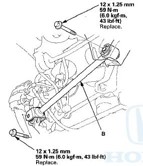
4. Install lower arm B in the reverse order of removal, and note these items: - First install all of the components, and lightly tighten the bolts, then raise the suspension to load it with the vehicle's weight before fully tightening to the specified torque.
- Make sure the clearance between lower arm B and the parking brake cable is more than 5 mm (0.2 in).
- Before installing the wheel, clean the mating surfaces on the brake disc and the inside of the wheel.
5. Check the wheel alignment, and adjust it if necessary (see page 18-5).
 Control Arm Replacement
1. Raise and support the vehicle {see page 1-13).
2. Remove the rear wheel.
3. Remove the control arm mounting self-locking nut (A)
and the washer (B) from the knuckle side.
NOTE; Use a new ...
 Stabilizer Link Removal/Installation
1. Raise and support the vehicle (see page 1 -13).
2. Remove the rear wheel.
3. Remove the flange nut (A) and the self-locking nut (B)
while holding the respective joint pin (C) with a hex
wre ...
See also:
TPMS Control Unit Replacement
NOTE: Make sure the TPMS control unit mounting
bracket is not bent or twisted as this may affect its
communication with the tire pressure sensors.
1. Turn the ignition switch to LOCK (0).
2. R ...
HFL System Troubleshooting
NOTE:
• Before doing this troubleshooting, refer to General Troubleshooting
Information (see page 23-254) to make sure the
phone is compatible and configured correctly.
• You must be ...