 Honda Accord: Control Arm Replacement
1. Raise and support the vehicle {see page 1-13).
2. Remove the rear wheel.
3. Remove the control arm mounting self-locking nut (A) and the washer (B) from the knuckle side.
NOTE; Use a new self-locking nut during reassembly.
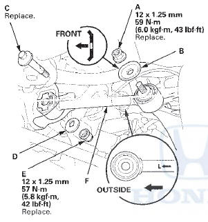
4. Mark the cam positions of the adjusting bolt (C) and the adjusting cam plate (D) with the frame.
5. Remove the self-locking nut (E) while holding the adjusting bolt then remove the adjusting cam plate, the adjusting bolt, and the control arm (F).
NOTE: Use a new adjusting bolt and a new self-locking nut during reassembly.
6. Install the control arm in the reverse order of removal, and note these items: - First install all of the components, and lightly tighten the bolts and the nuts, then raise the suspension to load it with the vehicle's weight before fully tightening to the specified torque.
- Position the extended surfaces of the cam on the adjusting bolt and the adjusting cam plate facing down.
- Align the cam positions of the adjusting bolt and the adjusting cam plate with the marked positions on the frame when tightening the self-locking nut.
- Before installing the wheel, clean the mating surfaces on the brake disc and the inside of the wheel.
7. Check the wheel alignment, and adjust it if necessary (see page 18-5).
 Lower Arm A Replacement
1. Raise and support the vehicle (see page 1-13).
2. Remove the rear wheel.
3. Remove the parking brake cable mounting bolt (B).
4. Remove the lower arm A mounting bolts, then
remove lower a ...
 Lower Arm B Replacement
1 Raise and support the vehicle (see page 1-13).
2. Remove the rear wheel.
3. Remove the lower arm B mounting bolts, then
remove lower arm B.
NOTE: Use new mounting bolts during reassembly.
...
See also:
Your Vehicle at a Glance
Your Vehicle at a Glance
Your Vehicle at a Glance ...
Shifting
To shift from Park to any position,
press firmly on the brake pedal, and
press the release button on the front
of the shift lever, then move the
lever. You cannot shift out of Park
when th ...
If the Malfunction Indicator LampComes On or Blinks
• Reasons for the indicator lamp to come on or blink
• Comes on when there is a problem with the engine emissions control
system, or the fuel fill cap is missing, or loose.
• Blinks when ...