 Honda Accord: Low Oil Pressure Indicator Circuit Troubleshooting (Open)
1 Connect the Honda Diagnostic System (HDS) to the data Jink connector (DIG) (see step 2 on page 11-3).
2. Turn the ignition switch to ON (ll).
3. Make sure the HDS communicates with the vehicle and the engine control module (ECM)/powertrain control module (PCM). If It does not communicate, troubleshoot the DLC circuit (see page 11-181).
4. Check for DTCs (see page 11-3). If a DTC Is present, diagnose, and repair the cause before continuing with this test.
5. Check the OIL PRESSURE SWITCH in the PGM-FI DATA LIST with the HDS.
Is ON Indicated? YES-Replace the gauge control module (see page 22-351 ) . NO-Go to step 6.
6. Turn the ignition switch to LOCK (0).
7. Check the oil pressure switch (see page 8-9).
Is the oil pressure switch OK? YES-Go to step 8.
NO-Replace the oil pressure switch (see page 8-9).
8. Turn the ignition switch to ON (II), and jump the SCS line with the HDS, then turn the ignition switch to LOCK (0).
NOTE: This step must be done to protect the ECM/PCM from damage.
9. Disconnect ECM/PCM connector B (49P) and the oil pressure switch connector.
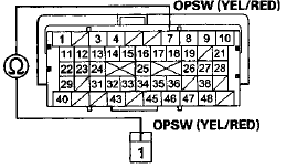
10. Check for continuity between ECM/PCM connector terminal B7 and the oil pressure switch connector.
ECM/PCM CONNECTOR B (49P)
Terminal side of female terminals

OIL PRESSURE SWITCH CONNECTOR
Wire side of female terminal
Is there continuity? YES-Update the ECM/PCM if it does not have the latest software (see page 11-203), or substitute a known-good ECM/PCM (see page 11-7), then recheck.
If the symptom/indication goes away with a known-good ECM/PCM, replace the original ECM/PCM (see page 11-204).
NO-Repair open in the wire between the oil pressure switch connector and ECM/PCM connector terminal B7.
 Low Oil Pressure Indicator Circuit Troubleshooting (Short)
1. Connect the Honda Diagnostic System (HDS) to the
data link connector (DLC) (see step 2 on page 11-3).
2. Turn the ignition switch to ON (II).
3. Make sure the HDS communicates with the vehic ...
See also:
Fuse Locations
UNDER-HOOD FUSE BOX
INTERIOR FUSE BOX (Driver’s Side)
INTERIOR FUSE BOX (Passenger’s Side) ...
Dashboard Center Vent
Removal / Installation
Special Tools Required
KTC Trim Tool Set SOJATP2014*
*Available through the Honda Tool and Equipment
Program; call 888-424-6857
With Navigation Sf stem
NOTE:
- Take care not to scratch the dashb ...
SRS Unit Update
Special Tools Required
• Honda Diagnostic System (HDS) tablet tester
• Honda Interface Module (HIM) and an iN workstation
with the latest HDS software version
• HDS pocket tester
Ð ...

