 Honda Accord: Key Interlock System Circuit
Troubleshooting
Produced in USA models
NOTE: SRS components are located in the area. Review the SRS component locations 4-door {see page 24-21), 2-door (see page 24-23), and precautions and procedures (see page 24-25) before doing repairs or servicing.
1. Move the shift lever to P and set the parking brake.
2. Remove the column cover (see page 20-181).
3. Turn the ignition switch to ACCESSORY (I).
4. Disconnect the steering lock assembly BP connector.
5. Check if the ignition switch can be turned to LOCK (0).
Can the ignition switch be turned to LOCK (0)? YES—Go to step 6.
NO-Replace the ignition key cylinder/steering lock assembly (see page 17-16.
6 Make sure the ignition switch is turned to LOCK (0).
7 Disconnect connector Q (20P) from the driver's under-dash fuse/relay box.
8. Check for continuity between steering lock assembly 6P connector terminal No. 3 and body ground.
STEERING LOCK ASSEMBLY 6P CONNECTOR
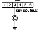
Wire side of female terminals
Is there continuity? YES
-Repair a short to body ground in the wire between the key interlock solenoid and the driver's MICU. NO
-Go to step 9.
9. Remove the center console panel (see page 20-157).
10. Disconnect the A/T gear position indicator panel light/park-pin switch 6P connector.
11. Check for continuity between A/T gear position indicator panel light/park-pin switch 6P connector terminal No. 1 and body ground.
A/T GEAR POSITION INDICATOR PANEL LIGHT/PARK-PIN SWITCH 6P CONNECTOR
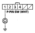
Wire side of female terminals
Is there continuity? YES
-Repair a short to body ground in the wire between A/T gear position indicator panel light/park-pin switch 6P connector terminal No. 1 and the driver's MlCU.
NO
-Goto step 12.
12. Check for continuity between A/T gear position indicator panel light/park-pin switch 6P connector terminal No. 2 and body ground.
A/T GEAR POSITION INDICATOR PANEL LIGHT/PARK-PIN SWITCH 6P CONNECTOR
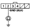
Wire side of female terminals
Is there continuity? NO
-Goto step 13.
YES
-Repair an open or high resistance in the wire between AT gear position indicator panel light/park-pin switch and body ground (G503).
13. Check f o r continuity between A/T gear position indicator panel light/park-pin switch 6P connector terminals No. 1 and No. 2. Do not push the shift lever button.
A / T G E A R P O S I T I O N I N D I C A T O R P A N EL L I G H T / P A R K - P I N S W I T C H 6 P C O N N E C T OR
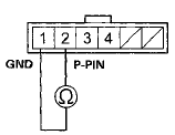
Terminal side of male terminals
Is there continuity when the shift lever is out of P, and continuity when shifted into P? YES
-Go to step 14.
NO
-Replace the park pin switch (see page 14-258).! 14. Disconnect driver's under-dash fuse/relay box connector F (33P).
15. Check for continuity between driver's under-dash fuse/relay box connector F (33P) terminal No. 4 and body ground.
D R I V E R S U N D E R - D A S H F U S E/ RELAY B O X C O N N E C T O K F (33P)
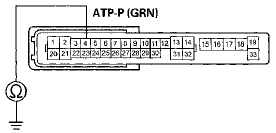
Wire side of female terminals
Is there continuity? YES
-Repair a short to ground in the wire.
NO
-Go to step 16.
16. Remove the transmission range switch cover (see step 7 on page 14-238).
17. Disconnect the transmission range switch 10P connector.
18. Check for continuity between driver's under-dash fuse/relay box connector F (33P) terminal No. 4 and transmission range switch 10P connector terminal No. 6.
D R I V E R ' S U N D E R - D A S H F U S E/ RELAY B O X C O N N E C T O R F (33P)
Wire side of female terminals
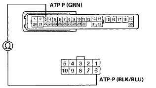
T R A N S M I S S I O N R A N G E S W I T C H 1 0 P C O N N E C T OR
Terminal side of female terminals
Is there continuity? YES
-Go to step 19.
NO
-Repair an open or high resistance in the wire between the driver's under-dash fuse/relay box and the transmission range switch.
19. At the transmission range switch, check for continuity between terminals No. 6 and No. 10.
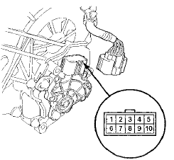
Is there continuity? YES-
Go to step 20.
NO-
Check the transmission range switch adjustment and retest. If still no continuity, replace the transmission range switch (see page 14-240).
20. Check for continuity between transmission range switch harness terminal No. 10 and body ground.
Is there continuity? YES
-Substitute a known-good driver's under-dash fuse/relay box and retest.
NO
-Repair an open or high resistance in the wire between the transmission range switch and body ground (G101).
Produced in Saitama models
NOTE: SRS components are located in the area. Review the SRS component locations 4-door (see page 24-21), 2-door (see page 24-23), and precautions and procedures (see page 24-25) before doing repairs or servicing.
1. Move the shift lever to P and set the parking brake.
2. Remove the column cover (see page 20-181).
3. Turn the ignition switch to ACCESSORY (I).
4. Disconnect the steering lock assembly BP connector.
5. Check if the ignition switch can be turned to LOCK (0).
Can the ignition switch be turned to LOCK (0)? YES
-Go to step 6.
NO-
Replace the ignition key cylinder/steering lock assembly (see page 17-1 B).
6. Make sure the ignition switch is turned to LOCK (0).
7. Disconnect connector Q (20P) from the driver's under-dash fuse/relay box.
8. Check for continuity between steering lock assembly BP connector terminal No. 3 and body ground.
STEERING LOCK ASSEMBLY 6P CONNECTOR
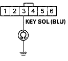
Wire side of female terminals
Is there continuity? YES
-Repair a short to body ground in the wire between the key interlock solenoid and the driver's MICU.
NO
-Go to step 9.
9. Remove the center console panel (see page 20-157).
10. Disconnect the A/T gear position indicator panel light/park-pin switch BP connector.
11. Check for continuity between A/T gear position indicator panel light/park-pin switch 6P connector terminal No. 1 and body ground.
A/T GEAR POSITION INDICATOR PANEL LIGHT/PARK-PIN SWITCH SP CONNECTOR
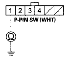
Wire side of female terminals
Is there continuity? YES
-Repair a short to body ground in the wire between A/T gear position indicator panel light/park-pin switch 6P connectorterminal No. 1 and the driver's MICU.
NO
-Go to step 12.
12. Check for continuity between A/T gear position indicator panel light/park-pin switch 6P connector terminal No. 2and body ground.
A/T GEAR POSITION INDICATOR PANEL LIGHT/PARK-PIN SWITCH 6P CONNECTOR
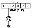
Wire side of female terminals
Is there continuity? NO
-Go to step 13.
YES
-Repair an open or high resistance in the wire between AT gear position indicator panel light/park-pin switch and body ground (G503).
13. Check for continuity between A/T gear position indicator panel light/park-pin switch 6P connector terminals No. 1 and No. 2. Do not push the shift lever button.
A/T GEAR POSITION INDICATOR PANEL LIGHT/PARK-PIN SWITCH 6P CONNECTOR
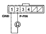
Terminal side of male terminals
Is there continuity when the shift lever is out of P, and no continuity when shifted into P? YES
-Go to step 14.
NO
-Replace the park pin switch (see page 14-258).H 14. Disconnect driver's under-dash fuse/relay box connector F (33P).
15. Check for continuity between driver's under-dash fuse/relay box connector F (33P) terminal No. 4 and body ground.
DRIVERS UNDER-DASH FUSE/ RELAY BOX CONNECTOR F (33P)
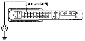
Wire side of female terminals
Is there continuity? YES
-Repair a short to ground in the wire.
NO
-Go to step 16.
16. Remove the transmission range switch cover (see step 7 on page 14-238).
17. Disconnect the transmission range switch 10P connector.
18. Check for continuity between driver's under-dash fuse/relay box connector F (33P) terminal No. 4 and transmission range switch 10P connector terminal No. 6.
DRIVERS UNDER-DASH FUSE/ RELAY BOX CONNECTOR F (33P)
Wire side of female terminals
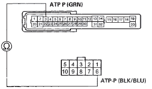
TRANSMISSION RANGE SWITCH 10P CONNECTOR
Terminal side of female terminals
Is there continuity? YES
-Go to step 19.
NO
-Repair an open or high resistance in the wire between the driver's under-dash fuse/relay box and the transmission range s w i t c h.
19. At the transmission range switch, check for continuity between terminals No. 6 and No. 10.
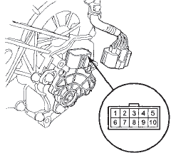
Is there continuity? YES-
Go to step 20.
NO
-Check the transmission range switch adjustment (see step 8 on page 14-240) and retest. If still no continuity, replace the transmission range switch (see page 14-240).
20. Check for continuity between transmission range switch harness terminal No. 10 and body ground.
Is there continuity? YES
-Substitute a known-good driver's under-dash fuse/relay box and retest.
NO
-Repair an open or high resistance in the wire between the transmission range switch and body ground (G101
 Circuit Diagram
...
 Key Interlock Solenoid Test
NOTE: SRS components are located in this area. Review
the SRS component locations for 4-door (see page
24-21),for 2-door (see page 24-23), and the precautions
and procedures (see page 24-25) before ...
See also:
Front Door Glass and Regulator
Replacement
NOTE: Put on gloves to protect your hands.
1. Remove the door panel:
- 2-door (see page 20-12)
- 4-door {see page 20-17)
2.2-door: Remove the screws, then remove the door
panel bracket (A).
...
Instrument Visor Removal/Installation
Special Tools Required
KTC Trim Too! Set SOJATP2014*
*Available through the Honda Tool a n d Equipment
Program; call 888-424-6857
NOTE:
- Take care not to scratch the dashboard or the related
pa ...
Engine Speed Limiter
If you exceed the maximum speed
for the gear you are in, the engine
speed will enter into the tachometer’s
red zone. If this occurs, you may feel
the engine cut in and out. This is
caused ...
