 Honda Accord: Function Test
NOTE; • With climate control: Before testing, troubleshoot the B-CAN System Diagnosis Test Mode A (see page 22-134).
• Before testing, check the No. 4 (40 A) fuse in the under-hood fuse/relay box and the No. 16 (7.5 A) fuse in the driver's under-dash fuse/relay box.
• Be careful not to scratch or damage the defogger wires with the tester probe.
1. Turn the ignition switch to ON (II), then turn the rear window defogger switch ON.
2. Measure the voltage between the positive terminal (A) and body ground. There should be battery voltage.
• If there is no voltage, check for:
- Faulty climate control unit, driver's climate control switch ('10 model), passenger's climate control switch ('08-09 models), or HVAC control unit.
- An open or high resistance in the GRN wire to the positive terminal.
• If there is voltage, go to step 3.
3. Measure the voltage between the negative terminal (B) and body ground. There should be less than 0.2 V.
If there is greater than 0.2 V, check for an open in the BLK wire or poor ground (G801). If there is 0.2 V or less, go to step 4.
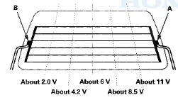
4. Touch the voltmeter positive probe along each defogger wire, and the negative probe to the negative terminal.
• If the voltage is as specified, the defogger wire up to that point is OK.
• If the voltage is not as specified, repair the defogger wire.
- If voltage is more than specified at one of the points, there is a break in the negative half of the wire.
- If voltage is less than specified at one of the points, there is a break in the positive half of the wire.
 Circuit Diagram
'10 model w i t h navigation system
'08-09 models with navigation system
Without navigation system with climate control system
With HVAC control system
...
 Defogger Wire Repair
NOTE: To make an effective repair, the broken section
must be no longer than 1.0 in (25 mm).
1. Lightly rub the area around the broken section (A)
with fine steel wool, then clean it with isoprop ...
See also:
Engine Installation
Special Tools Required
- Universal Lifting Eyelet 07AAK-SNAA120
Engine Hanger Adapter VSB02C000015
Engine Support Hanger, A and Reds AAR-T-1256*
Subframe Adapter VSB02C000016
Subframe Alignment P ...
Headliner Removal/Installation
Special Tools Required
KTC Trim Tool Set SOJATP2014*
*Available through the Honda Tool and
Equipment
Program; call 888-424-6857
SRS components are located in this area. Review the
SRS component ...
Maintenance Main Items
If message "SERVICE" does not appear more than 12 months after the display is
reset change the engine oil every year.
NOTE:
- Independent of the maintenance messages in the smart maint ...