 Honda Accord: DTC Troubleshooting
DTC B10CF:
Left Daytime Running Lights Circuit Malfunction
NOTE: • Make sure the No. 15 (7.5 A) fuse in the driver's under-dash fuse/relay box is OK.
• If you are troubleshooting multiple DTCs, be sure to follow the instructions in B-CAN System Diagnosis Test Mode A (see page 22-134).
1. Clear the DTCs with the HDS.
2. Turn the ignition switch to LOCK (0).
3. Release the parking brake lever.
4. Turn the headlight switch OFF.
5. Turn the ignition switch to ON (II).
Is DTC B10CF indicated? YES
-Go to step 6.
NO
-lntermittent failure, the system is OK at this time.
Check for loose or poor connections.H 6. Turn the headlight high beam ON.
Does the left headlight (high beam) come on? YES
-Go to step 7.
NO
-Go to step 9.
7. Turn the ignition switch to LOCK (0).
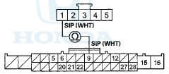
8. Measure voltage between body ground and driver's under-dash fuse/relay box connector Q (20P) terminals No.l and No. 2, and between body ground and driver's under-dash fuse/relay box connector R (24P) terminals No. 2 and No. 5 individually.
DRIVER'S UNDER-DASH FUSE/RELAY BOX CONNECTOR Q (20P)
Wire siae or Temaie terminals
DRIVER'S UNDER-DASH FUSE/RELAY BOX CONNECTOR R (20P)
Wire side of female terminals
Is there less than 0.2V? YES
-Faulty driver's MICU; replace the driver's under-dash fuse/relay box, USA models (see page 22-86), Canada models (see page 22-87).
NO
-Repair an open or high resistance in the wire or poor ground (G501, G502).
9. Turn the ignition switch to LOCK (0).
10. Turn the headlight switch OFF.
11. Check the No. 28 (10 A) fuse in the driver's under-dash fuse/relay box.
Is the fuse OK? YES
-Go to step 12.
NO
-Replace the fuse, and recheck. If the fuse is blown again, repair a short in the wire.
12. Check the left headlight bulb.
Is the bulb OK? YES
-Go to step 13.
NO
-Replace the bulb and recheck .
13. Disconnect driver's under-dash fuse/relay box connector F (33P).
14. Disconnect the left headlight (high beam) 2P connector.
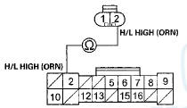
15. Check for continuity between driver's under-dash fuse/relay box connector F (33P) terminal No. 13 and left headlight (high beam) 2P connector terminal No. 2.
LEFT HEADLIGHT (HIGH BEAM) 2P CONNECTOR
Wire side of female terminals
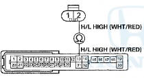
DRIVER'S UNDER-DASH FUSE/RELAY BOX CONNECTOR F (33P)
Wire side of female terminals
Is there continuity? YES
-Go to step 16.
NO
-Repair an open or high resistance in the wire.
16. Check for continuity between left headlight (high beam) 2P connector terminal No. 1 and body ground.
LEFT HEADLIGHT (HIGH BEAM) 2P CONNECTOR
Wire side of female terminals
Is there continuity? YES
-Faulty driver's MICU; replace the driver's under-dash fuse/relay box, USA models (see page 22-86), Canada models (see page 22-87).
NO
-Repair an open or high resistance in the wire or poor ground (G302).
DTC B11CF:
Right Daytime Running Lights Circuit Malfunction
NOTE: If you are troubleshooting multiple DTCs, be sure to follow the instructions in B-CAN System Diagnosis Test Mode A (see page 22-134).
1. Clear the DTCs with the HDS.
2. Turn the ignition switch to LOCK (0).
3. Release the parking brake lever.
4. Turn the headlight switch OFF.
5. Turn the ignition switch to ON (II).
Is DTC B11CF indicated? Y E S
- G o to step 6.
NO
-lntermittent failure, the system is OK at this time.
Check for loose or poor connections H 6. Turn the headlight high beam ON.
Does the right headlight come on? Y E S
- G o to step 7.
NO
-Go to step 9.
7. Turn the ignition switch to LOCK (0).
8. Measure voltage between body ground and passenger's under-dash fuse/relay box connector A (38P) terminals No. 36 and No. 37, and between body ground and connector E (18P) terminals No. 15 and No. 16 individually.
PASSENGER'S UNDER-DASH FUSE/RELAY BOX CONNECTOR A (38P)
Wire side of female terminals
PASSENGERS UNDER-DASH FUSE/RELAY BOX CONNECTOR E (18P)
Wire side of female terminals
Is there less than 0.2V? Y E S
- F a u l t y passenger's M I C U ; replace the passenger's under-dash fuse/relay box (see page 22-89).B NO
-Repair an open or high resistance in the wire or poor ground (G201, G505) .
9. Turn the ignition switch to LOCK (0).
10. Turn the headlight switch OFF.
11. Check the No. 1 (10 A) fuse in the passenger's under-dash fuse/relay box.
Is the fuse OK? Y E S
- G o to step 12.
NO
-Replace the fuse, and recheck. If the fuse is blown again, repair a short in the wire.
12. Check the right headlight bulb.
Is the bulb OK? YES-
Go to step 13.
NO
-Replace the bulb and recheck.
13. Disconnect passenger's under-dash fuse/relay box connector E (18P).
14. Disconnect the right headlight (high beam) 2P connector.
15. Check for continuity between passenger's under-dash fuse/relay box connector E (18P) terminal No. 2 and right headlight (high beam) 2P connectorterminal No. 2.
R I G H T H E A D L I G H T ( H I G H B E A M ) 2 P C O N N E C T OR
Wire side of female terminals
PASSENGER'S U N D E R - D A S H F U S E / R E L AY B O X C O N N E C T O R E (18P)
Wire side of female terminals
Is there continuity? YES
-Go to step 16.
NO
-Repair an open in the w i r e .
16. Check for continuity between right headlight (high beam) 2P connector terminal No. 1 and body ground.
R I G H T H E A D L I G H T ( H I G H B E A M ) 2 P C O N N E C T OR
Wire side of female terminals
Is there continuity? YES
-Faulty passenger's MICU; replace the passenger's under-dash fuse/relay box (see page 22-89).
NO
-Repair an open or high resistance in the wire or poor ground (G203).
DTC B1275:
Headlight Switch OFF Position Circuit Malfunction
DTC B127S:
Combination Light Headlight Switch Parking Light Position Circuit Malfunction
DTC B1277:
Headlight Switch AUTO Position Circuit Malfunction
DTC B1278;
Headlight Switch ON Position Circuit Malfunction
NOTE: If you are troubleshooting multiple DTCs, be sure to follow the instructions in B-CAN System Diagnosis Test Mode A (see page 22-134).
1. Ciear trie u i c s with the HDS.
2. Turn the ignition switch to LOCK (0) and then back to ON (II).
3. Turn the combination light switch to the PARKING (SMALL), AUTO, and ON (low beam) positions, and then to the OFF position.
4. Wait for 6 seconds or more.
5. Check for DTCs with the HDS.
Are DTCs B1275, B1276, B1277, and/or B1278 indicated? YES
-Go to step 6.
NO
-lntermittent failure, the system is OK at this time.
Check for loose or poor connections.
6. Select LIGHTING from the BODY ELECTRICAL system select menu, and enter the DATA LIST.
7. Check each combination light switch position value with the DATA LIST menu.
When the combination light switch is turned OFF
When the combination light switch is turned to PARKING LIGHT
When the combination light switch is turned to AUTO
When the combination light switch is turned ON (HEADLIGHT)
Are all data list values correct? YES
-Faulty driver's MICU; replace the driver's under-dash fuse/relay box, USA models (see page 22-86), Canada models (see page 22-87).
NO
-Go to step 8.
8. Turn the Ignition switch to LOCK (0).
9. Disconnect the combination light switch 12P connector.
10. Turn the ignition switch to ON (II).
11. Select LIGHTING from the BODY ELECTRICAL system select menu, and enter the DATA LIST.
12. Check each combination light switch position value with the DATA LIST menu.
Are all data list values indicated OFF? YES
-Go to step 16.
NO
-Go to step 13.
13. Turn the ignition switch to LOCK (0).
14. Disconnect driver's under-dash fuse/relay box connector R (24P).
15. Check for continuity between body ground and driver's under-dash fuse/relay box connector R (24P) terminals No. 6, No. 7, and No. 8 individually.
DRIVER'S UNDER-DASH FUSE/RELAY BOX CONNECTOR R (20P)
Wire side of female terminals
Is there continuity? YES
-Repair a short to ground in the wire.
NO
-Faulty driver's MICU; replace the driver's under-dash fuse/relay box, USA models (see page 22-86), Canada models (see page 22-87)
16. Turn the ignition switch to LOCK (0).
17. Do the combination light switch test (see page 22-232).
Is the combination light switch OK? YES
-Go to step 18.
NO
-Replace the combination light switch.
18. Disconnect driver's under-dash fuse/relay box connector R (24P).
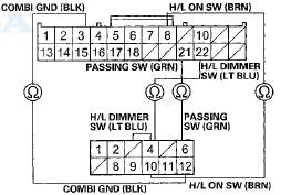
19. Check for continuity between driver's under-dash fuse/relay box connector R (24P) terminals and combination light switch 12P connector terminals as shown:
COMBINATION LIGHT SWITCH 12P CONNECTOR
Wire side of female terminals
DRIVER'S UNDER-DASH FUSE/RELAY BOX CONNECTOR R (24P)
Wire side of female terminals
Is there continuity? YES
-Go to step 20.
NO
-Repair an open or high resistance in the wire.
20. Check for continuity between driver's under-dash fuse/relay box connector R (24P) terminals as shown:
Is there continuity? YES
-Repair a short between the wires.
NO-
Faulty driver's MICU; replace the driver's under-dash fuse/relay box, USA models (see page 22-86), Canada models (see page 22-87).
DTC B1279:
Dimmer Switch Circuit Malfunction
NOTE: If you are troubleshooting multiple DTCs, be sure to follow the instructions in B-CAN System Diagnosis Test Mode A (see page 22-134).
1. Clear the DTCs with the HDS.
2. Turn the ignition switch to LOCK (0) and then back to ON (II).
3. Turn the combination light (headlight) switch ON.
4. Change the dimmer switch from low beam to high beam.
5. Turn the combination light switch OFF, and then to the passing position, and wait for at least 6 seconds.
6. Check for DTCs with the HDS.
Is DTC B1279 indicated? YES
-Go to step 7.
NO
-lntermittent failure, the system is OK at this time.
Check for loose or poor connections.
7. Select LIGHTING from the BODY ELECTRICAL system select menu, then enter the DATA LIST.
8. Check each combination light switch position value with the DATA LIST menu.
When the passing switch is operated
When the headlight switch is turned ON, and the dimmer switch changed from low beam to high beam
Are all data list values correct? YES
-Faulty driver's MICU; replace the driver's under-dash fuse/relay box, USA models (see page 22-86), Canada models (see page 22-87).H NO
-Go to step 9.
9. Turn the ignition switch to LOCK (0).
10. Disconnect the combination light switch 12P connector.
11. Turn the ignition switch to ON (II).
12. Select LIGHTING from the BODY ELECTRICAL system select menu, then enter the DATA LIST.
13. Check each combination light switch position value with the DATA LIST menu.
When the combination light switch is turned OFF
Are all data list values indicated OFF?
YES
-Go to step 17.
NO
-Go to step 14.
14. Turn the ignition switch to LOCK (0).
15. Disconnect under-dash fuse/relay box connector R (24P).
16. Check for continuity between body ground and driver's under-dash fuse/relay box connector R (24P) terminals No. 8, No. 21, and No. 22 individually.
DRIVER'S UNDER-DASH FUSE/RELAY BOX CONNECTOR R (20P)
Wire side of female terminals
Is there continuity? YES
-Repair a short to ground in the wire.
NO
-Faulty driver's MICU; replace the driver's under-dash fuse/relay box, USA models (see page .
22-86), Canada models (see page 22-87).
17. Turn the ignition switch to LOCK (0).
18. Do the combination light switch test (see page 22-232).
Is the combination light switch OK? YES
-Go to step 19.
NO
-Replace the combination light switch (see page 22-232).
19. Disconnect driver's under-dash fuse/relay box connector R (24P).
20. Check for continuity between driver's under-dash fuse/relay box connector R (24P) terminals and the combination light switch 12P connector terminals as shown:
DRIVER'S UNDER-DASH FUSE/RELAY BOX CONNECTOR R (24P)
Wire side of female terminals
COMBINATION LIGHT SWITCH 12P CONNECTOR
Wire side of female terminals
Is there continuity? YES
-Go to step 21.
NO
-Repair an open or high resistance in the wire.
21. Check for continuity between driver's under-dash fuse/relay box connector R (24P) terminals as shown:
Is there continuity? YES
-Repair a short between the w i r e s . NO
-Faulty driver's MICU; replace the driver's under-dash fuse/relay box, USA models (see page 22-86), Canada models (see page 22-87).
DTC B1575:
Auto Light Sensor Circuit Malfunction
1. Clear the DTCs with the HDS.
2. Turn the ignition switch to LOCK (0) and then back to ON (II).
3. Wait for one second.
4. Check for DTCs with the HDS.
is DTC B1575 indicated? YES
-Go to step 5.
NO
-lntermittent failure, the system is OK at this time.
Check for loose or poor connections.
5. Turn the ignition switch to LOCK (0).
6. Disconnect the automatic lighting/sunlight sensor 5P connector.
7. Turn the ignition switch to ON (II).
8. Measure the voltage between body ground and automatic lighting/sunlight sensor 5P connector terminal No. 1.
AUTOMATIC LIGHTING/SUNLIGHT SENSOR 5P CONNECTOR
Wire side of female terminals
Is there about 5V? YES-
Replace the automatic lighting/sunlight sensor (see page21-186).
NO
-Go to step 9.
9. Turn the ignition switch to LOCK (0).
10. Disconnect passenger's under-dash fuse/relay box connector D (28P).
11 Check for continuity between passenger's under-dash fuse/relay box connector D (28P) No. 9 terminal and automatic lighting/sunlight sensor 5P connector terminal No. 1.
AUTOMATIC LIGHTING/SUNLIGHI SENSOR 5P CONNECTOR
Wire side of female terminals
PASSENGER'S UNDER-DASH FUSE/RELAY BOX CONNECTOR D (28P)
Wire side of female terminals
Is there continuity? YES
-Faulty passenger's MICU. Substitute a known-good passenger's under-dash fuse/relay box and recheck.
NO
-Repair an open or high resistance in the wire.
 Circuit Diagram
With automatic lighting
Without automatic lighting
Back-up Lights
Brake Lights
...
 MICU Input Test
NOTE:
• Before testing, troubleshoot the multiplex
integrated control unit first, using B-CAN System Diagnosis Test Mode A
{see page 22-134).
• Before testing, make sure the No. 15 (7 ...
See also:
Random Play
To play the tracks on the current
disc in random order, select TRACK
RANDOM, and press ENTER on the
interface selector. As a reminder,
you will see RANDOM next to
TRACK on the screen. To tur ...
Playing the FM/AM Radio (Models with navigation system)
Playing the FM/AM Radio (Models with navigation system) ...
Wiper Motor Replacement
Removal
1. Open the hood. Remove the caps (A) and nuts (B).
NOTE: The illustration shows 4-door.
2. Close the hood, then spread protective cloths (A) on
the hood to avoid scratching the hood e ...