 Honda Accord: Bearing Installation
Special Tools Required
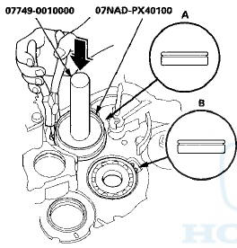
-Attachment, 78 x 80 mm 07NAD-PX40100
-Driver Handle, 15 x 135L 07749-0010000
-Bearing Driver Attachment, 42 x 47 07746-0010300
1. Install the bearings in the direction shown.
2. Expand each snap ring using snap ring pliers, and install the mainshaft bearing (A) and the countershaft bearing (B) part-way into the housing using the driver handle and the 78 x 80 mm attachment.
3. Release the snap ring pliers, then push the bearing down into the transmission housing until the snap ring snaps in place around it.
4. Expand the snap ring of the secondary shaft bearing (A) and handle the idler gear shaft bearing (B) using the snap ring pliers, and install the bearing part-way into the housing using the driver handle and the 42 x 47 mm bearing driver attachment.
5. Release the snap ring pliers, then push the bearings down into the transmission housing until the snap ring snaps in place around it.
6. After installing the bearings check that the snap rings (A) are seated in the bearing and the transmission housing grooves, and that the snap ring end gaps (B).
are correct.
7. Install the idler gear shaft (see page 14-297).
 Bearing Removal
Special Tools Required
•Attachment, 78x80 mm 07NAD-PX40100
-Driver Handle, 15 x 135L 07749-0010000
-Bearing Driver Attachment, 42 x 47 07746-0010300
1. Remove the idler gear shaft (see page 1 ...
 Reverse Idler Gear Removal and
Installation
Reverse Idler Gear Removal and
Installation
Removal
1. Remove the bolt (A) securing the reverse idler gear
shaft holder (B).
2. Install a 5 x 0.8 mm bolt (C) in the reverse idler gear
shaft (D), and pull it to remove the reverse idler gea ...
See also:
Symptom Troubleshooting Index
Power Door Locks/Kef less
1. Check for B-CAN DTCs. If any B-CAN DTCs are Indicated, refer to the B-CAN
System Diagnosis Test Mode A (see page
22-134) and resolve them first.
2. If the door lock ...
Mainshaft Bearing and Oil Seal
Replacement
Special Tools Required
-Adjustable Bearing Puller, 2 5 - 4 0 mm 07736-A01000B
-Driver Handle, 15 x 135L 07749-0010000
-Attachment, 62 x 68 mm 07746-0010500
-Attachment, 72 x 75 mm 07746-0010600
1 ...
Component Location Index
4-door with moonroof
2-door with moonroof
...