 Honda Accord: System Description
Overview
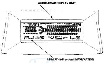
The electrical compass shows the azimuth information in 8-directions (N, NE, E, SE, S, SW, W, NW) to the audio-HVAC display unit via the audio unit.
Starting Operation
When the ignition switch is turned to ACCESSORY (1), the electrical compass unit begins to communicate with the audio unit. Then turn the ignition switch to ON (II), the self-test mode begins automatically.
The self-test function checks for the current voltage, non-volatile memory (NVM), and ROM status in the electrical compass unit. If the unit detects a malfunction while in the self-test, it indicates a malfunction by flashing compass information segments (CAL and NW) in the audio-HVAC display unit The electrical compass unit send the azimuth (direction) information to the audio unit The electrical compass unit receive the VSP signal from the gauge control module via the audio unit The azimuth information is fixed while parked.
Self-Calibration
The electrical compass unit has a self-calibration function. It detects and compensates for magnetic anomalies caused by bridges, subways and large steel structures. When the vehicle leaves an area with a strong magnetic interference field (2,400 mG or more), the electrical compass unit automatically begins calibrating. If needed, you can manually calibrate the compass.
Zone Selection
Zone selection is required to compensate for the difference between magnetic North and geographic North. This deviation is referred to as declination, the compass compensates for declination when you select the zone where the vehicle is located.
System Diagram
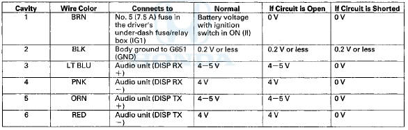
Electrical Compass Unit Connector Inputs and Outputs
Electrical Compass Unit SP Connector

 Circuit Diagram
...
See also:
Power Mirror Heaters
All Canadian models
U.S. EX, EX-L and all V6 models
The outside mirrors are heated to
remove fog and frost. With the
ignition switch in the ON (II)
position, turn on the heaters by
pressi ...
Shifting
Change the shift position in accordance with your driving needs.
• Shift lever positions
You cannot turn the ignition switch to LOCK
and remove the key unless the shift lever is in
.
The ...
Manual Transmission
On models with 5-speed manual
transmission, or models
with 6-speed manual transmission
The manual transmission is
synchronized in all forward gears for
smooth operation. It has a lockout so ...