 Honda Accord: Alternator Overhaul
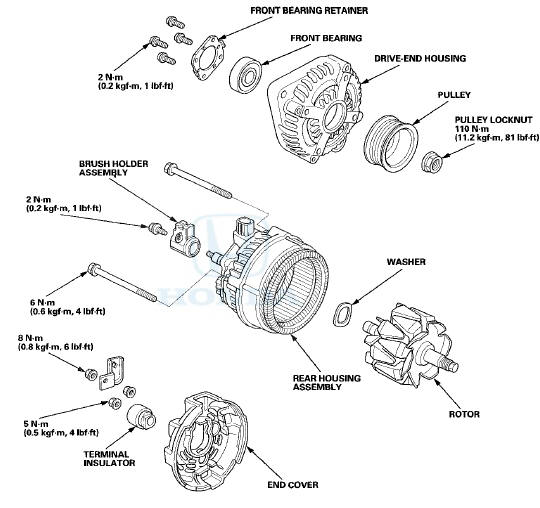
Exploded View
Special Tools Required
- Driver Handle, 15 x 135L 07749-0010000
- Bearing Driver Attachment, 42 x 47 mm 07746-0010300
NOTE: Refer to the Exploded View as needed during this procedure.
1. Test the alternator and regulator before you remove them (see page 4-27).
2. Remove the alternator (see page 4-32).
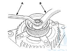
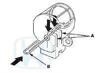
3. If the front bearing needs replacing, remove the pulley locknut with a 10 mm wrench (A) and a 22 mm wrench (B). If necessary, use an impact wrench.
4. Remove the harness stay and the three flange nuts from the alternator.
5. Remove the end cover.

6. Remove the brush holder assembly (A).
7. Remove the four through bolts, then remove the rear housing assembly (A) and the washer (B).
8. If you are not replacing the front bearing, go to step 13. Remove the rotor from the drive-end housing.
9. Inspect the rotor shaft for scoring, and Inspect the bearing journal surface in the drive-end housing for seizure marks.
- If the rotor Is damaged, replace the rotor assembly.
- If the rotor is OK, go to step 10.
10. Remove the front bearing retainer.
11. Drive out the front bearing with a brass drift and a hammer.
12. Install a new front bearing in the driver-end housing with a hammer, the driver handle, 15 x 135L, and the bearing driver attachment, 42 x 47 mm.
Alternator Brush Inspection
13. Measure the length of both brushes (A) with a venier caliper (B).
- If either brush is shorter than the service limit, replace the brush holder assembly.
- If the brush length is OK, go to step 14.
Alternator Brush Length
Standard (New): 10.5 mm (0.41 in)
Service Limit: 1.5 mm (0.06 in)
Rotor Slip Ring Test
14. Check for continuity between the slip rings (A).
- If there is continuity, go to step 15.
- If there is no continuity, replace the rotor assembly.
15. Check for continuity between each slip ring and the rotor (B) and the rotor shaft (C).
- If there is no continuity, replace the rear housing assembly, then go to step 16.
- If there is continuity, replace the rotor assembly.
Alternator Reassembly
16. If you removed the pulley, put the rotor in the drive-end housing, then torque its locknut to 110 N-m (11.2 kgf-m, 81.0 Ibfft).
17. Remove any grease or oil from the slip rings.
18. Put the rear housing assembly and the drive-end housing/rotor assembly together, and tighten the four through bolts.
19. Push the brushes (A) in, then insert a pin or drill bit (B) (about 1.6 mm (0.06 in) diameter) to hold them there.
20. Install the brush holder assembly, and pull out the pin or drill bit.
21. Install the end cover.
22. After assembling the alternator, turn the pulley by hand to make sure the rotor turns smoothly and without noise.
23. Install the alternator (see page 4-33) and the drive belt (see page 4-30).
 Alternator Removal and
Installation
Alternator Removal and
Installation
Removal
1. Do the battery terminal disconnection procedure (see
page 22-91).
2. Remove the drive belt (see page 4-30).
3. Remove the two bolts securing the alternator.
4. Disconnect the alt ...
 Cruise Control
...
See also:
Driving Position Memory System
U.S. V6 models, and Canadian EX-L and
V6 models with navigation system
Your vehicle has a memory feature
for the driver’s seat position.
Seat, except for power lumbar,
position can be stored ...
Valve, Spring, and Valve Seal
Removal
Special Tools Required
Valve Spring Compressor Attachment 07757-PJ1010A
Identify the valves and the valve springs as they are
removed so that each item can be reinstalled in its
original position. ...
Multi-Information Display Warning andInformation Messages
The following messages appear only on the multi-information display. Press
the (information) button to see the
message again
with the system message indicator on.
...