 Honda Accord: Sleep and Wake-up Mode Test
1. Shift to the sleep mode: Close all doors. Turn the ignition switch to LOCK (0), and remove the key, then open and close the driver's door. If the MICU receives no further inputs listed below, it will go into sleep mode in less than 40 seconds.

2. Confirm the sleep mode: NOTE: Check any official Honda service website for more information about parasitic draw at the battery.
Measure the voltage on the B-CAN communication line (PNK and BLU wires); there should be battery voltage in the sleep mode. Check the parasitic draw at the battery while shifting into the sleep mode; amperage should change from about 200 mA to less than 35 mA in less than 40 seconds.
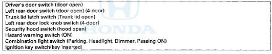
3. Shift to the wake up mode: When the ignition switch is turned to ON (II), the driver's MICU, passenger's MICU, gauge control module, immobilizer-keyless control unit, and ECM/PCM wake up at the same time without "talking" to each other through the communication lines. When any switch in the multiplex integrated control system is turned on, it wakes up its related control unit which, in turn, wakes up the other units. After confirming the sleep mode, look in the following table for the switch most related to the problem. Operate that switch and see if its control unit wakes up.
NOTE: If any control unit is faulty and will not wake up, several circuits in the system will malfunction at the same time. In the table below, the control unit is followed by a list of the switches and input signals that can wake it up.
 B-CAN System Diagnosis Test Mode
1 and Test Mode 2 (without the
HDS)
B-CAN System Diagnosis Test Mode
1 and Test Mode 2 (without the
HDS)
Special Tools Required
MFCS (MCIC) Service Connector 07WAZ-00101 OA
Test Mode 1
Check the ECM/PCM for DTCs and troubleshoot
ECM/PCM (see p a g e 11-3) or F-CAN loss o f
communication errors first ...
 Circuit Diagram
...
See also:
Tensioner Pulley
Replacement
1. Remove the auto-tensioner (see page 4-31).
2. Clamp the auto-tensioner (A) by using two 8 mm bolts
(B) and a vise (C) as shown. Do not clamp the
auto-tensioner itself, then remove the tensione ...
Lower Arm B Replacement
1 Raise and support the vehicle (see page 1-13).
2. Remove the rear wheel.
3. Remove the lower arm B mounting bolts, then
remove lower arm B.
NOTE: Use new mounting bolts during reassembly.
...
Rear License Plate Light Bulbs
When replacing, use the following bulbs.
1. Remove the license plate light assembly by
pushing the left edge of the lens toward the
right and pulling the assembly out.
2. Remove the lens b ...