 Honda Accord: B-CAN System Diagnosis Test Mode
1 and Test Mode 2 (without the
HDS)
Honda Accord: B-CAN System Diagnosis Test Mode
1 and Test Mode 2 (without the
HDS)
Special Tools Required
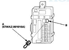
MFCS (MCIC) Service Connector 07WAZ-00101 OA
Test Mode 1
Check the ECM/PCM for DTCs and troubleshoot ECM/PCM (see p a g e 11-3) or F-CAN loss o f communication errors first, then do this diagnosis if the HDS is not available.
1. Check the No. 15 (10 A) fuse in the under-hood fuse/relay box and No. 5 (7.5 A) fuse in the driver's under-dash fuse/relay box.
Are the fuses OK? YES
-Go to step 2.
NO
-Find and repair the cause of the blown f u s e .
2. Remove the driver's dashboard lower cover (see page 20-166).
3. Turn the ignition switch to ON (II), and move the ceiling light switch to the middle (door) position. .
4. Connect the MPCS service connector (A) to the MICU service check connector socket (B) in the driver's under-dash fuse/relay box.
5. Wait 5 seconds, and watch the ceiling light. When the ceiling light flashes quickly once and then goes off, the system is in Test Mode 1.
6. Check for B-CAN DTCs indicated by the gauge control module odo/trip display while still in Test Mode 1.
Press the SEL/RESET button to display the next code.
After you get to the last code, the display shows END.
If no DTCs are stored, the display will read NO (see page 22-109).
NOTE: If the test times out, remove the MPCS service connector, turn the ignition switch to LOCK (0), and repeat steps 3 and 4.
Are any DTCs indicated? YES
-Go to step 7.
NO
-Go to step 10.
7. Record all DTCs and troubleshoot them in this order:
• Battery voltage DTCs
• Internal error DTCs
• Loss of communication DTCs
• Signal error DTCs
8. Clear the DTCs by pressing and holding the SEL/RESET button for at least 10 seconds.
9. You will hear a beep to confirm the codes have been cleared. Operate the devices that failed, and recheck for codes.
Test Mode 2
10. Remove the MPCS service connector from the driver's under-dash fuse/relay box MICU service check connector socket for 5—10 seconds, then re-insert it to enter Mode 2. When the system enters Mode 2, the ceiling light flashes two times quickly and then goes off.
NOTE: If the MPCS service connector is disconnected for too short or too long of a time, or the ignition switch is turned to LOCK (0), the system returns to Test Mode 1.
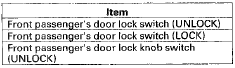
1 1 . The following tables list the circuits that can be checked in Test Mode 2. Operate the switch that is most closely related to the problem. If the circuit is OK, the ceiling light will blink once. If the circuit is faulty, there will be no indication.
Drivers MICU

Passenger's MICU
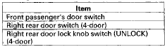
Door Multiplex Control Unit
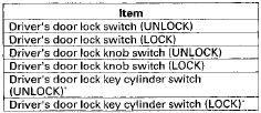
* A second key is necessary to check the key cylinder inputs. Be sure to rotate the key cylinder switch two times to each position (lock and lock, unlock and unlock) to ensure the door lock knob switch is in the appropriate position.
Front Passenger's Power Window Switch
Does the ceiling light work properly in all switch positions? YES
-Go to function and input test for the system related to the f a i l u r e . NO
-Repair the open, short, or replace the faulty switch.
 B-CAN System Diagnosis Test Mode
D
B-CAN System Diagnosis Test Mode
D
Do this diagnosis if a component that is controlled by the
B-CAN system does not work or come on.
NOTE:
• If the component does not turn off or stop, go to
B-CAN System Diagnosis Test Mode ...
 Sleep and Wake-up Mode Test
1. Shift to the sleep mode:
Close all doors. Turn the ignition switch to LOCK (0), and remove the key, then
open and close the driver's door. If the
MICU receives no further inputs listed below, i ...
See also:
Audio Disc Changer
Removal/Installation
With Navigation
NOTE:
• Put on gloves to protect your hands.
• Take care not to scratch the dashboard and related
parts.
• Lay a shop towel under the parts when working on
the ...
Valve Stem-to-Guide Clearance
Inspection
1. Remove the valves (see page 6-86).
2. Subtract the O.D. of the valve stem, measured with a
micrometer, from the I.D. of the valve guide,
measured with an inside micrometer or a ball gauge.
...
Transmission Installation
Special Tools Required
-Engine Hanger Adapter VSB02C000015*
•Engine Support Hanger, A and Reds
AAR-T1256*
-Subframe Adapter VSB02C000016
-Subframe Alignment Pin 070AG-SJAA10S
*: Available ...