 Honda Accord: DTC Troubleshooting Index
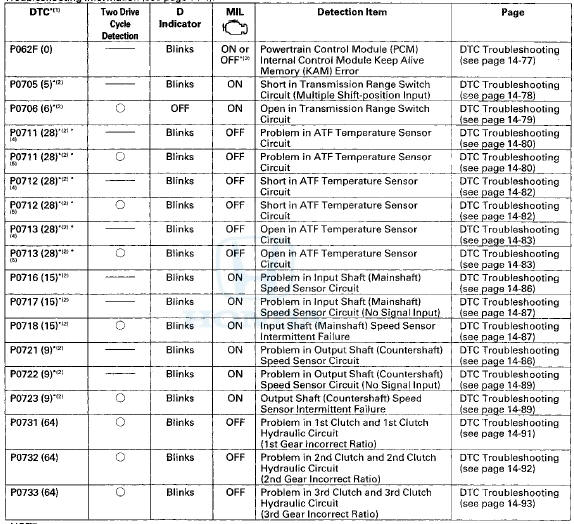
NOTE: Before you troubleshoot record all freeze data and any on-board snapshot with the HDS, and review General Troubleshooting Information (see page 14-4).
NOTE:
*1: The DTC in parentheses is the flash code the D indicator indicates when the data link connector (DLC) is connected to the HDS, and in the SCS mode.
*2: This code is caused by an electrical circuit problem and cannot be caused by a mechanical problem in the transmission.
*3: The MIL comes on when the PGM-FI system detects the same failure.
*4: '08-09 models
*5: '10 model
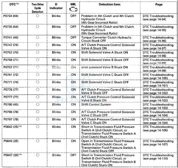
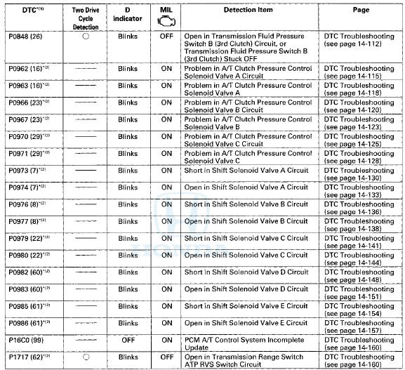
 General Troubleshooting Information
How to Check for DTCs with the Honda
Diagnostic S f stem (HDS)
When the powertrain control module (PCM) senses an
abnormality in the input or output system, the D
indicator (A) in the gauge contro ...
 Symptom Troubleshooting Index
NOTE: Do an all DTC check with the HDS and troubleshoot those first before
following the repair procedures listed in the
index.
...
See also:
Rear Power Window Motor Test
1. Remove the rear power window switch (see page
22-307).
2. Test the motor in each direction by connecting battery
power and ground to the rear power window switch
14P connector (A) according t ...
Center Display Visor
Removal / Installation
Special Tools Required
KTC Trim Tool Set SOJATP2014*
*Available through the Honda Tool and
Equipment
Program; call 888-424-6857
Without Navigation System
NOTE:
- Take care not to scratch the d ...
Safety Labels
Label Locations
These labels are in the locations shown. They warn you of potential hazards
that can cause serious injury or death. Read these labels
carefully.
If a label comes off or becomes h ...