 Honda Accord: Countershaft Assembly Clearance Inspection
tightened to the specified torque (see page 13-46).
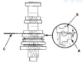
1. Measure the clearance between 1st gear (A) and the 1st gear distance collar (B) with a feeler gauge (C).
- If the clearance exceeds the service limit, go to step 2.
- If the clearance is within the service limit, go to step 4.
Standard: 0.06-0.16 mm (0.002-0.006 in)
Service Limit: 0.25 mm (0.010 in)
2. Measure the length of the 1st gear distance collar as shown.
- If the length is not within the standard, replace the 1st gear distance collar.
- If the length is within the standard, go to step 3.
Standard: 23.03-23.08 mm (0.907-0.909 in)
3. Measure the thickness of 1 st gear.
- If the thickness is less than the service limit, replace 1st gear. * - If the thickness is within the service limit, replace the 1st/2nd synchro hub and the reverse gear as a set.
Standard: 22.92~22.97 mm (0.902-0.904 In)
Service Limit: 22.87 mm (0.900 in)
4. Measure the clearance between 2nd gear (A) and 3rd gear (B) with a feeler gauge (C). If the clearance exceeds the service limit, go to step 5.
Standard: 0.06-0.16 mm f i . i i 2 - i . i i 6 in)
Service Limit: 0.25 mm (0.010 in)
5. Measure the length of the 2nd gear distance collar.
- If the length is not within the standard, replace the 2nd gear distance collar.
- If the length is within the standard, go to step 6.
Standard: 28.03-28.08 mm (1.104-1.106 in)
6. Measure the thickness of 2nd gear.
- If the thickness is less than the service limit, replace 2nd gear.
- If the thickness is within the service limit, replace the 1st/2nd synchro hub and reverse gear a s a set.
Standard: 27.92-27.97 mm (1.099-1.101 in)
Service Limit: 27.87 mm (1.097 in)
 Mainshaft Reassembly
Exploded View
*: The components of the double cone synchro assembly.
Special Tools Required
- Driver Handle, 40 mm I.D. 07746-0030100
-СћBearing Driver Attachment, 30 mm
07746-0030300
NOTE: ...
 Countershaft Disassembly
NOTE: Refer to the Exploded View in the Countershaft
Reassembly, as needed, when removing components
pressed onto the countershaft (see page 13-46).
1. Securely clamp the countershaft assembly In ...
See also:
Checking Wiper Blades
If the wiper blade rubber has deteriorated, it will leave streaks and the
metal wiper
arm may scratch the window glass. ...
Front HFL-Navigation-ANC
Microphone
Removal/Installation
NOTE:
• Put on gloves to protect your hands.
• Take care not to scratch the dashboard and related
parts.
• Lay a workshop towel under the parts when working
on them to protect ...
Horn Test/Replacement
1. Remove the grille cover;
•2-door (see page 20-274)
• 4-door (see page 20-274)
2. Disconnect the 1P connector (A) from each horn (B).
3. Test the horn by momentarily connecting L _.t ...