
 Honda Accord: Mainshaft Reassembly
Exploded View
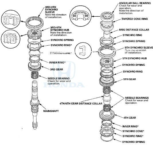
*: The components of the double cone synchro assembly.
Special Tools Required
- Driver Handle, 40 mm I.D. 07746-0030100
-СћBearing Driver Attachment, 30 mm 07746-0030300
NOTE: Refer to the Exploded View, as needed, during this procedure.
1. Clean all the parts in solvent, dry them, and apply MTF to all contact surfaces.
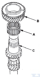
2. Install the needle bearing (A) and 3rd gear (B) onto the mainshaft (C).
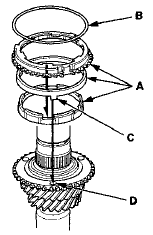
3. Install the double cone synchro assembly (A) with the synchro spring (B) by aligning the synchro cone fingers (C) with the holes (D) in 3rd gear.
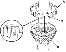
4. Install the 3rd/4th synchro hub (A) by aligning the synchro ring fingers (B) with the grooves (C) in the 3rd/4th synchro hub.
NOTE: Make sure to install the 3rd/4th synchro hub in the direction shown.
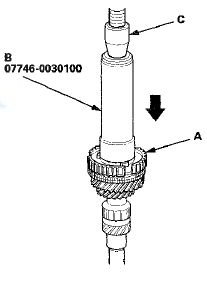
5. Press on the 3rd/4th synchro hub (A) using the 40 mm I.D. driver handle (B) and a press (C).
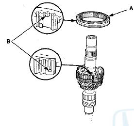
6. Install the 3rd/4th synchro sleeve (A) by aligning the stops (B) of the 3rd/4th synchro sleeve and the 3rd/4th synchro hub. After installing, check the operation of the 3rd/4th synchro hub set.
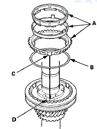
7. Install the double cone synchro assembly (A) with the synchro spring (B) by aligning the synchro ring fingers (C) with the grooves (D) in the 3rd/4th synchro hub.
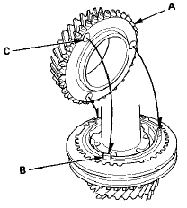
8. Install 4th gear (A) by aligning the synchro cone fingers (B) with the holes (C) in 4th gear.
9. Install the 4th/5th gear distance collar (A) with the needle bearings (B) and 5th gear (C).
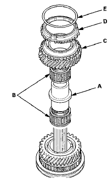
10. Install the synchro ring (D) with the synchro spring (E) onto 5th gear.
11. Install the 5th synchro hub (A) by aligning the synchro ring fingers (B) with the grooves (C) in the 5th synchro hub.
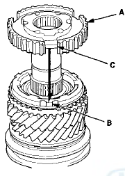
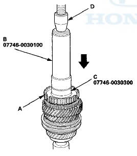
12. Press on the 5th synchro hub (A) using the 40 mm I.D.
driver handle (B), the 30 mm bearing driver attachment (C), and a press (D).
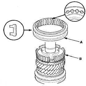
13. Install the 5th synchro sleeve (A) by aligning the slots of the 5th synchro sleeve and the 5th synchro hub (B).
After installing, check the operation of the 5th synchro hub set.
NOTE: Make sure to align the slots in the 5th synchro hub as shown.
14. Install the synchro ring (A) with the synchro spring (B) by aligning the synchro ring fingers (C) with the grooves (D) in the 5th synchro hub.
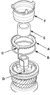
15. Install the MBS distance collar (E) and the tapered cone ring (F).
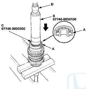
16. Press on a new angular ball bearing (A) using the 40 mm I.D. driver handle (B), the 30 mm bearing driver attachment (C), and a press (D).
 Mainshaft Inspection
1. Inspect the gear and bearing contact areas for wear
and damage, then measure the mainshaft at points A,
B, C, D, and E. If any part of the mainshaft is less than
the service limit, replace it.
...
 Countershaft Assembly Clearance Inspection
tightened to the specified torque (see page 13-46).
1. Measure the clearance between 1st gear (A) and the
1st gear distance collar (B) with a feeler gauge (C).
- If the clearance exceeds the se ...
See also:
Jump Starting
• Jump Starting Procedure
Turn off the power to electric devices, such as audio and lights. Turn off
the engine,
then open the hood.
1. Connect the first jumper cable to your
vehicle's bat ...
Power Transistor Test
1. Remove the passenger's dashboard undercover (see
page 20-170).
2. Disconnect the 4P connector from the power
transistor.
3. Measure the resistance between terminals No. 3 and
No. 4 of the ...
Rewriting the ODO Data and
Transferring the Maintenance
Minder Data to a New Gauge Control
Module
NOTE:
• Obtain a new gauge control module before starting
the rewriting process. Only new gauges can be
rewritten.
• Rewriting is not possible on a gauge control module
that will not ...