 Honda Accord: Center Pocket Removal/Installation
Without Navigation System
NOTE; - Take care not to scratch the dashboard or the related parts.
- A/T is shown; M/T is similar.
1. Remove the center console panel (see page 20-157).
2. A/T: Move the shift lever to 1st.
M/T: Move the shift lever to R.
3. Apply protective tapes (A) to the entire pocket lid face and the front area of the A/T gear position indicator panel (B) (A/T).
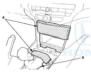
4. Open the lid, and remove the bolts securing the center pocket (A).
5. Pull out the center pocket (A), then remove it. Take care not to scratch the shift lever knob and the A/T gear position indicator panel (B) (A/T).


With Navigation System
N O T E : - Take care not to scratch the dashboard or the related parts.
- A/T is shown; M/T is similar.
1. Remove the center console panel (see page 20-157).
2. A/T: Move the shift lever to 1st.
M/T: Move the shift lever to R.
3. Open the lid, and remove the bolts securing the center pocket (A).
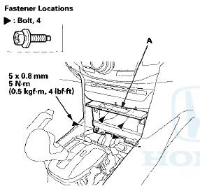
4. Pull out the center pocket (A), then remove it. Take care not to scratch the shift lever knob and the A/T gear position indicator panel (B) (A/T ).

5. Install the center pocket in the reverse order of removal.
 Driver's Inner Dashboard Trim
Removal/Installation
Driver's Inner Dashboard Trim
Removal/Installation
Special Tools Required
KTC Trim Tool Set SOJATP2014*
*Available through the Honda Tool and
Equipment
Program; call 888-424-6857
NOTE:
- Take care not to scratch the dashboard or the related
pa ...
 Dashboard Center Lower Cover
Removal/Installation
Dashboard Center Lower Cover
Removal/Installation
Special Tools Required
KTC Trim Tool Set SOJATP2014*
*Available through the Honda Tool and
Equipment
Program; call 888-424-6857
SRS components are located in this area. Review the
SRS component ...
See also:
Ball Joint Boot Inspection / Replacemen
Special Tools Required
- Clip Guide, 45 mm 070AG-SJA0300
-Clip Guide, 41 mm 07974-SA50700
1. Check the ball joint boot for weakness, damage,
cracks, and grease leaks.
NOTE:
- If the ball joint ...
Circuit Diagram
...
Shift Lever Installation
1. Install the shift lever assembly (A).
Type A Shift Lever
Type B Shift Lever
2. Connect the shift lock solenoid connector (B) and the
park pin switch/A/T gear position indicator panel light
...