 Honda Accord: Ball Joint Boot Inspection / Replacemen
Special Tools Required
- Clip Guide, 45 mm 070AG-SJA0300
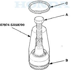
-Clip Guide, 41 mm 07974-SA50700
1. Check the ball joint boot for weakness, damage, cracks, and grease leaks.
NOTE: - If the ball joint boot is damaged with grease leaks, replace the appropriate part as an assembly.
- If the ball joint boot is soft and cracked without grease leaks, go to step 2. Replace the appropriate ball joint boot.
2. Disconnect the appropriate ball joint connection, and remove the component including the ball joint:
- The front knuckle (see page 18-14)
- The front upper arm (see page 18-19)
- The rear upper arm (see page 18-43)
3. Remove the boot clip and the boot.
4. Pack the interior and lip (A) of a new boot with grease.
Keep the grease off of the boot-to-housing mating surfaces (B).
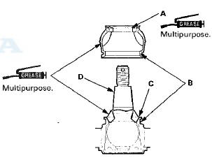
5. Pack fresh grease into the base (C). Do not let dirt or other foreign materials get into the boot.
6. Install the boot on the ball joint, then squeeze it gently to force out any air, then wipe the grease off the tapered portion of the ball joint pin (D).
7. The front knuckle ball joint or the rear upper arm ball joint: Adjust the depth by turning the clip guide until its base is just above the groove around (A) the bottom of the boot. Then slide the clip (B) over the clip guide and into position on the boot.
8. The front upper arm ball joint: Adjust the clip guide with the adjusting bolt (A) until its base is just above the groove around (B) the bottom of the boot. Then slide the clip (C) over the clip guide and into position on the boot.
9. After installing a boot wipe any grease off the exposed portion of the ball joint pin.
10. Install all of the removed parts.
 Ball Joint Removal
Special Tools Required
- Ball Joint Thread Protector, 14 mm 07AAE-SJAA100
- Ball Joint Thread Protector, 12 mm 07AAF-SDAA100
- Ball Joint Thread Protector, 10 mm 07AAF-SECA120
- Ball Joint Remover ...
 Front Suspension
...
See also:
Circuit Diagram
...
HazardWarning Button
Push the button between the center
vents to turn on the hazard warning
lights (four-way flashers). This
causes all four outside turn signals
and both turn indicators in the
instrument pane ...
Overheating
How to Handle Overheating
Overheating symptoms are as follows:
• The temperature gauge needle is at the
mark or the engine suddenly loses
power.
• Steam or spray comes out of the engine co ...