
 Honda Accord: Under-hood Fuse/Relay Box
Removal and Installation
Special Tools Required
Relay Puller 07AAC-000A1A0
NOTE; The under-hood fuse/relay box is a part of the left engine compartment wire harness, and it cannot be replaced by itself.
Removal
1. Do the battery terminal disconnection procedure (see page 22-91).
2. Open the cover (A), then remove the screws (B) for the alternator and battery cable terminals.
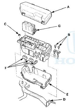
3. Remove the nut (C), and release the tab (D) bottom cover (E) from the under-hood fuse/relay box.
4. Disconnect the connectors (F) from the under-hood fuse/relay box.
5. Remove the relay circuit board (G) from the under-hood fuse/relay box.
6. Carefully remove the relays by prying under the base of the relay using the relay puller (see page 22-93).
NOTE: Do not use pliers. Pliers will damage the relays, which could cause the engine to stall or not start.
Installation
1. Install the relays and connect the connectors to the under-hood fuse/relay box, then install the under-hood fuse/relay box in the reverse order of removal.
2. Install the removed parts in the reverse order of removal.
3. Do the battery terminal reconnection procedure (see page 22-91).
4. Confirm that all systems work properly.
 Ground Distribution
Ground to Components Index
* 1 : EX-L, EX-L PZEV
*2: Except EX-L, EX-L PZEV
*3: With premium audio system
*4: With navigation system
*5: '10 model
*6: '08-09 models ...

See also:
DLC Circuit Troubleshooting
NOTE: If you suspect the HDS or the HDS DLC cable may
be the source of the communication probrem, verify that
they are working properly by connecting them to a
known-good, like vehicle and system, ...
Drive Belt Auto-tensioner
Inspection
Special Tools Required
Belt Tension Release Tool Snap-on YA9317 or
equivalent, commercially available
1. Turn the ignition switch to ON (II), and make sure to
turn the A/C switch OFF. Turn the ign ...
DTC Troubleshooting
DTC 11,13,15,17: Tire Low Air Pressure
NOTE: If low tire pressure is detected, the TPMS control
unit sets one or more of these DTCs, and turns on the
low tire pressure indicator. If the low tire pr ...