 Honda Accord: Transmission Removal
Special Tools Required
-Engine Hanger Adapter VSB02C000015*
-Engine Support Hanger, A and Reds AAR-T1256*
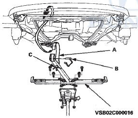
- Subframe Adapter VSB02C000016*
*: Available through the Honda Tool and Equipment Program 888-424-6857.
NOTE: -Use fender covers to avoid damaging painted surfaces.
-Special tool Reds engine support hanger AAR-T1256 must be used with the side engine mount installed.
1. Secure the hood in the wide open position with the support rod.
2. Do the battery removal procedure (see page 22-92).
3. Remove the front grille cover.
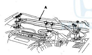
4. Remove the strut brace (A).
5. Remove the air cleaner housing (see page 11-332) and the intake air duct.
6. Remove the nut securing the under-hood fuse/relay box, and swing it out of the way.
7. Remove the battery base (see step 8 on page 5-3).
8. Raise the vehicle on a lift, and make sure it is securely supported.
9. Remove the front wheels.
10. Remove the splash shield.
11. Remove the drain plug (A), and drain the ATF.
12. Reinstall the drain plug with a new sealing washer (B).
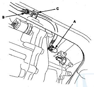
13. Disconnect the A/T clutch pressure control solenoid valve A connector (A) and the transmission fluid pressure switch A (2nd clutch) connector (B), and remove the harness clamps (C) from the clamp brackets (D).
14. Remove the transmission range switch subharness connector (A) from the connector bracket (B), then disconnect it.
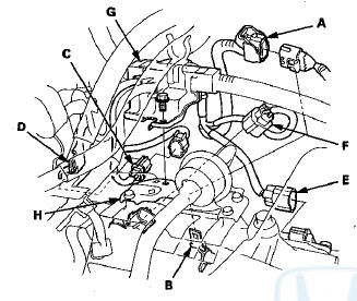
15. Remove the A/F sensor connector (C) from the connector bracket (D), then disconnect it.
16. Disconnect the input shaft (mainshaft) speed sensor connector (E) and the output shaft (countershaft) speed sensor connector (F).
17. Remove the harness cover bracket bolt, and remove the engine wire harness cover bracket (G) from the ATF filter bracket (H).
18. Disconnect the shift solenoid wire harness connector (A), the A/T clutch pressure control solenoid valve B connector (B), the A/T clutch pressure control solenoid valve C connector (C), and remove the harness clamp (D) from the clamp bracket (E).
19. Disconnect the ATF cooler hoses (A) from the ATF cooler lines (B). Turn the ends of the ATF cooler hoses up to prevent ATF from flowing out, then plug the ATF cooler hoses and the lines.
20. Check for any signs of leakage at the hose joints.
21. Disconnect the transmission fluid pressure switch B (3rd clutch) connector (A), and remove the harness clamp (B) from the clamp bracket (C).
22. Disconnect the vacuum hose (A).
23. Disconnect the ATF cooler hose (A) from the ATF cooler line (B). Turn the end of the ATF cooler hose up to prevent ATF from flowing out, then plug the hose and line.
24. Remove the ATF cooler hose (C) from the hose clamp (D).
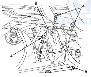
25. Remove the upper transmission mount bracket bolts.
NOTE: Do not remove the TORX bolt (A) from the upper transmission mount. If the TORX bolt is removed, the upper transmission mount must be replaced as an assembly.
26. Attach the engine hanger adapter (VSB02C000015) to the threaded hole located on the rear side of the cylinder head.
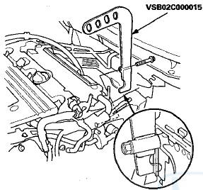
27. Install the engine support hanger (AAR-T1256) to the vehicle, and attach the hook (A) to the slotted hole in the engine hanger adapter (VSB02C000015). Tighten the wing nut (B) by hand to lift and support the engine.
NOTE: -Be careful when working around the windshield.
-Be careful not to damage the hood opener cable when installing the engine support hanger (AAR-T1256) at the front bulkhead.
28. Remove the vacuum hose (A) from the hose clamp (B).
29. Remove the front engine mount stop (C) and the clamp bracket (D), and remove the front engine mount bolt (E).
30. Remove the heat shield mounting bolts (A), then remove the heat shield (B).
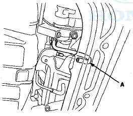
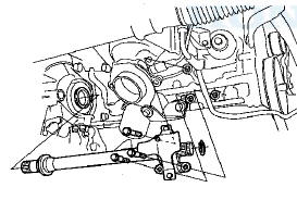
32. Remove the power steering (P/S) fluid return hose clamp bolt (A).
33. Remove the P/S fluid inlet line clamp bolt (B).
34. Remove the rear engine mount bolts (A), then remove the rear engine mount (B).
35. Remove the bolts (A), then remove the rear engine mount upper bracket (B).
36. Remove the steering gearbox stiffeners.
37. Remove the P/S fluid return line clamp bolt (A).
38. Release the P/S fluid return line (B) from the return line clamp (C).
39. Remove the bolts (B), and the self-locking nuts (C).
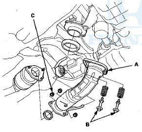
40. Remove exhaust pipe A.
41. Remove the damper pinch bolts (A), the damper fork mounting nuts (B), the bolts (C), and the damper forks (D) (see step 3 on page 18-21).
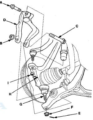
42. Remove the cotter pins (H) and the nuts (I), then separate the tie-rod end ball joints from the knuckles (see step 26 on page 17-41).
43. Remove the cotter pins (E) and the castle nuts (F) (see step 5 on page 18-21).
44. Separate the knuckle ball joints (G) from the lower arms (see step 6 on page 18-21).
45. Remove the torque converter cover (A), and remove the drive plate bolts (B) (8) while rotating the crankshaft pulley.
46. Vehicles with JHM VINs: Remove the shift cable cover (A).
47. Vehicles with JHM VINs: Remove the spring clip (B) and the control pin (C), and separate the shift cable end (D) from the selector control lever (E). Remove the two bolts securing the shift cable bracket (F).
48. Vehicles with 1HG VINs: Remove the shift cable cover (A), and remove the two bolts securing the shift cable bracket (B).
49. Vehicles with 1HG VINs: Pry up the lock tab of the lock washer (C), and remove the lock bolt (D) and the lock washer, then separate the shift cable (E) from the selector control shaft (F).
50. Hang the shift cable to the body with a strap.
NOTE: Do not bend the shift cable excessively.
51. Remove the transmission lower mount nuts.
52. Remove both sides front subframe mid-mount bolts.
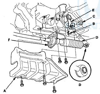
53. Support the steering gearbox on both sides with nylon straps.
54. Attach the front subframe adapter (VSB02C000016) to the front subframe by looping the strap (A) over the front of the front subframe, then secure the strap with the stop (B), then tighten the wing nut (C).
55. Raise a jack and line up the slots in the arms with the bolt holes on the corner of the jack base, then tighten the bolts.
56. Remove the four bolts (A) securing the stiffeners, and remove the four bolts (B) securing the front subframe, then lower the front subframe.
57. Place a jack under the transmission.
58. Remove the transmission lower mount.
59. Remove the left side driveshaft from the differential and the right side driveshaft from the intermediate shaft. Coat all precision machined surfaces with clean engine oil, then put plastic bags over the driveshaft ends. Support the driveshafts on both sides with nylon straps.
60. Remove the intermediate shaft. Coat all precision machined surfaces with clean engine oil, then put plastic bags over the intermediate shaft ends.
61. Remove the rear engine mount bracket.
62. Remove the front engine mount bracket.
63. Remove the jack.
64. Remove the upper transmission housing mounting bolts.
65. Lower the transmission by loosening the wing nut on the engine support hanger, and tilt the engine just enough for the transmission to clear the side frame.
Check that the transmission is completery free of the ATF cooler hoses, the vacuum hoses, and the electrical wiring.
66. Place the jack under the transmission.
67. Remove the front and lower transmission housing mounting bolts.
68. Remove the crankshaft position (CKP) sensor cover.
69. Remove the rear transmission housing mounting bolts.
NOTE: Be careful not to damage the CKP sensor and the sensor harness.
70. Check once again that the transmission is free of the vacuum hoses, the ATF cooler hoses, and the electrical wiring.
71. Slide the transmission away from the engine to remove it from the vehicle.
72. Remove the torque converter, the O-ring, and the dowel pins.
73. Inspect the drive plate, and replace it if it is damaged.
 ATF Replacement
NOTE: Keep all foreign particles out of the transmission.
1. Park the vehicle on level ground.
2. Warm up the engine to normal operating temperature
(the radiator fan comes on), and turn the en ...
 Drive Plate Removal and Installation
1. Remove the transmission assembly (see page
14-194).
2. Remove the drive plate (A) and the washer (B) from
the engine.
3. Install the drive plate and the washer on the engine,
and tighten t ...
See also:
Adjusting the Steering Wheel
The steering wheel height and distance from your body can be adjusted so that
you
can comfortably grip the steering wheel in an appropriate driving posture.
1. Pull the steering wheel adjustmen ...
Playing a USB Flash Drive
Your audio system reads and plays sound files on a USB flash drive in either
MP3,
WMA, or AAC*1 format.
Connect your USB flash drive to the USB port, then select the USB mode.
• How to Sel ...