 Honda Accord: A/T Gear Position Indicator Panel Light
Harness Replacement
Honda Accord: A/T Gear Position Indicator Panel Light
Harness Replacement
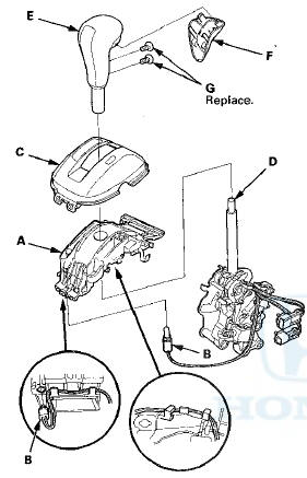
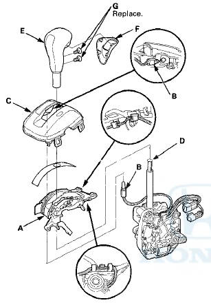
Type A Shift Lever
NOTE: The A/T gear position indicator panel light harness and the park pin switch are not available separately. Replace the A/T gear position indicator panel light harness and the park pin switch as a set.
1. Remove the center console (see page 20-158).
2. Remove the shift lever assembly (see page 14-222).
3. Wrap the end of a flat-tip screwdriver with tape, pry the shift lever knob cover locks, then remove the shift lever knob cover (A).
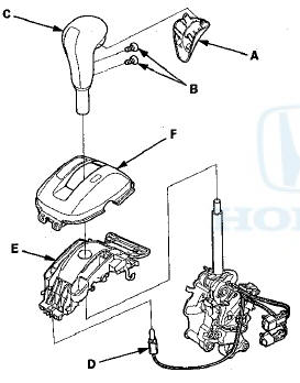
4. Remove the screws (B), and remove the shift lever knob (C) from the shift lever.
5. Remove the A/T gear position indicator panel light socket (D) from the indicator panel base (E).
6. Remove the A/T gear position indicator panel light harness from the harness guides of the indicator panel base.
7. Remove the A/T gear position indicator panel base, then disassemble the indicator panel (F) and the indicator panel base.
8. Release the lock (A) of the shift lock release, and remove the shift lock release and the release spring (B).
9. Remove the screw (A), and cut the harness wire tie (B), and remove the light bulb (C) from the socket.
10. Remove the park pin switch/A/T gear position indicator panel light harness (D).
11. Install a new park pin switch/A/T gear position indicator panel light harness, and secure the park pin switch with a new screw.
12. Tie the park pin switch/A/T gear position indicator panel light harness and the shift lock solenoid harness at the guide with a new harness wire tie.
13. Install the A/T gear position indicator panel light bulb in the socket.
14. Install the release spring (A) in the shift lock release (B).
15. Install the shift lock release and the release spring on the release shaft end.
16. Make sure that the release spring end (A) is installed in the shift lock release (B), and the hooked end (C) is on the stop (D).
17. Install the A/T gear position indicator panel base (A).
18. Route the park pin switch/A/T gear position indicator panel light harnesses. Take the slack out of the harnesses, and secure the harnesses with the harness wire tie at the harness guides.
19. Install the A/T gear position indicator panel light socket (B) in the indicator panel base.
20. Install the A/T gear position indicator panel (C).
21. Apply silicone grease to the top (D) of the shift lever rod.
NOTE: Make sure not to get any silicone grease on the terminal part of the connectors and switches, especially if you have silicone grease on your hands of gloves.
22. Install the shift lever knob (E) over the shift lever.
23. Install the shift lever knob cover (F) on the shift lever knob with new screws (G).
24. Install the shift lever (see page 14-224).
25. Install the center console (see page 20-158).
Type B Shift Lever
NOTE: The A/T gear position indicator panel light harness and the park pin switch are not available separately. Replace the A/T gear position indicator panel light harness and the park pin switch as a set.
1. Remove the center console (see page 20-158).
2. Remove the shift lever assembly (see page 14-222).
3. Wrap the end of a flat-tip screwdriver with tape, pry the shift lever knob cover locks, then remove the shift lever knob cover (A).
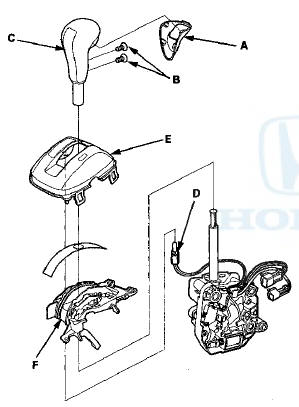
4. Remove the screws (B), and remove the shift lever knob (C) from the shift lever.
5. Remove the A/T gear position indicator panel light socket (D) from the indicator panel (E).
6. Remove the A/T gear position indicator panel light harness from the harness guides of the indicator panel base.
7. Remove the A/T gear position indicator panel base (F), then disassemble the indicator panel and the indicator panel base.
8. Remove the light bulb (A) from the socket.
9. Remove the park pin switch/A/T gear position indicator panel light harness (B) and the shift lock solenoid harness (C) from the harness guide (D).
10. Install a new park pin switch/A/T gear position indicator panel light harness.
11. Route the park pin switch/A/T gear position indicator panel light harness and the shift lock solenoid harness in the harness guide.
12. Install the A/T gear position indicator panel light bulb in the socket.
13. Install the A/T gear position indicator panel base (A).
14. Insert the A/T gear position indicator panel light socket (B) through the indicator panel base hole, then install the socket in the indicator panel ( C ) .
15. Route the park pin switch/A/T gear position indicator panel light harnesses. Take the slack out of the harnesses, and secure the harnesses in the harness guides.
16. Install the A/T gear position indicator panel.
17. Apply silicone grease to the top (D) of the shift lever rod.
NOTE; Make sure not to get any silicone grease on the terminal part of the connectors and switches, especially if you have silicone grease on your hands of gloves.
18. install the shift lever knob (E) over the shift lever.
19. Install the shift lever knob cover (F) on the shift lever knob with new screws (G).
20. Install the shift lever assembly (see page 14-224).
21. Install the center console (see page 20-158).
 Transmission Range Switch
Replacement
Transmission Range Switch
Replacement
1. Raise the vehicle on a lift, or apply the parking brake,
block the rear wheels, and raise the front of the
vehicle. Make sure it is securely supported.
2. Remove the left front wheel.
3. Mo ...

See also:
Symptom Troubleshooting Index
Find the symptom in the chart below, and do the related procedures in the
order listed until you find the cause.
...
Component Location Index
2-door
4-door
...
Selector Centre! Sheft Bearing
Replacement
Special Tools Required
•Driver Handle, 15 x 135L 07749-0010000
-Attachment, 22 x 24 mm 07746-001A800
1. Remove the oil seal from the end cover, then remove
the bearing.
2. Install a new be ...