 Honda Accord: Transmission End Cover
End Cover Installation
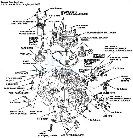
Exploded View
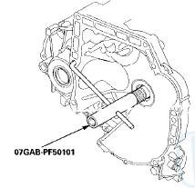
Special Tools Required
Mainshaft Holder 07GAB-PF50101
NOTE: Refer to the Exploded View as needed during the following procedure.
1. Install the mainshaft holder onto the mainshaft.
2. Lubricate the following parts with ATF: -Splines and threads of the mainshaft.
-Splines of the mainshaft idler gear.
-The old conical spring washer and the old locknut.
3. Install the mainshaft idler gear (A), the old conical spring washer (B), and the old locknut (C) on the mainshaft (D), and tighten the locknut to 226 N-m (23.0 kgfm, 166 Ibf-ft).
NOTE: -Do not tap the mainshaft idler gear to install.
-Use a torque wrench to tighten the locknut. Do not use an impact wrench.
4. Install the park lever spring (A), the park lever (B)f and the park lever stop (C) on the selector control shaft (D), then install the lock bolt with a new lock washer (E).
Do not bend the lock tab of the lock washer until step 18.
5. Install the park pawl shaft (F), the park pawl spring (G), the park pawl (H), and the stop shaft (I) on the transmission housing.
6. Lubricate the following parts with ATF: -Threads and splines of the countershaft.
-The old conical spring washer and the old locknut.
-Areas where the park gear contacts the conical spring washer.
7. Install the park gear (J), the old conical spring washer (K), and the old locknut (L) on the countershaft (M).
8. Lift the park pawl up, and engage it with the park gear, then tighten the locknut to 226 N-m (23.0 kgf-m, 166 Ibf-ft).
NOTE: -Do not tap the park gear to install.
-Use a torque wrench to tighten the locknut. Do not use an impact wrench.
-Countershaft locknut has left-hand threads.
9. Remove the locknuts and the conical spring washers from the mainshaft and the countershaft.
10. Lubricate the threads of the shafts, new locknuts, and new conical spring washers with ATF.
11 Install conical spring washers (A) with facing stamped mark side up in the direction shown, and install the mainshaft locknut (B), the countershaft locknut (C), and the secondary shaft locknut (D).
12. Tighten the locknuts to 167 N-m (17.0 kgf-m, 123 Ibfft).
NOTE: -Be sure to install the conical spring washers in the direction shown.
-Use a torque wrench to tighten the locknut. Do not use an impact wrench.
-Countershaft and secondary shaft locknuts have left-hand threads.
13. Remove the mainshaft holder from the mainshaft.
14. Stake the locknuts into the shafts to a depth (A) of 0.7-1.3 mm (0.03-0.05 in) using a 3.5 mm punch (B).
15. VIN begins with JHM: Install the selector control lever (A) on the selector control shaft (B), and install the bolt with a new lock washer (C), then bend the lock tab of the lock washer against the bolt head.
16. Set the park lever in the P position, then check that the park pawl (A) engages the park gear (B).
17. If the park pawl does not engage fully, do the park lever stop inspection and adjustment (see page 14-265).
18. Tighten the lock bolt (C), and bend the lock tab of the lock washer (D) against the bolt head.
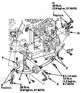
19. Install the ATF feed pipe (A) into the idler gear shaft, and install the ATF lubrication pipe (B) into the transmission housing.
20. Install a new gasket (A) on the transmission housing, and install the two dowel pins (B) and new O-rings (C) over the top of the ATF feed pipes.
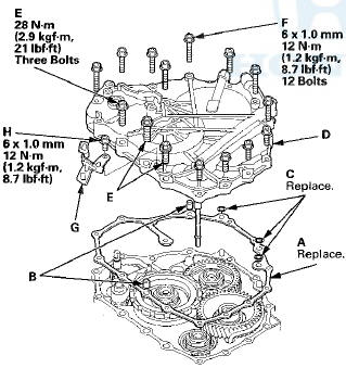
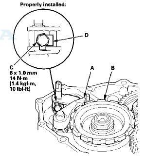
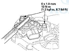
21. Install the end cover (D), and tighten the three special bolts (E) and the 6 x 1.0 mm bolts (F) (12 bolts).
22. Install the harness clamp bracket (G) on the end cover with the bolt (H).
23.-Move the selector control shaft (A) from the P position to the N position by turning the selector control shaft on the torque converter side.
NOTE: Do not squeeze the end of the selector control shaft tips together when turning the shaft. If the tips are squeezed together it will cause a faulty shift position signal or position due to the play between the selector control shaft and the transmission range switch.
24. Align the cutouts (A) on the rotary-frame with the neutral positioning cutouts (B) on the transmission range switch (C), then put a 2.0 mm (0.08 in) feeler gauge blade (D) in the cutouts to hold in the N position.
NOTE: Be sure to use a 2.0 mm (0.08 in) blade or equivalent to hold the transmission range switch in the N position.
25. Install theiransmission range switch (A) gently on'the selector control shaft (B) while holding it in the N position with the 2.0 mm .(6.08 in) blade (C).
26. Tighten the bolts on the transmission range switch while you continue to hold it in the N position. Do not move the transmission range switch when tightening the bolts. Remove the feeler gauge.
27. Connect the transmission range switch connector (A) securely, then install the harness clamps (B) on the clamp bracket (C).
28. Install the transmission range switch cover (D).
29. Clean the mounting surface and the fluid passage of A/T clutch pressure control solenoid valve A and the transmission housing.
30. Install a new gasket (B) on the transmission housing, and install the ATF pipe (C) and the ATF joint pipes (D).
NOTE: Be sure to install a new gasket with the blue side toward the transmission housing.
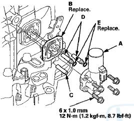
31. Install new O-rings (E) over the ATF joint pipes, and install A/T clutch pressure control solenoid valve A.
32. Clean the mounting surface and the fluid passage of A/T clutch pressure control solenoid valves B and C and the transmission housing.
33. Install a new gasket (A) and the ATF joint pipes (D) on the transmission housing, and install new O-rings (E) over the ATF joint pipes.
NOTE: Be sure to install a new gasket with the blue side toward the transmission housing.
34. Install A/T clutch pressure control solenoid valves B and C with the harness clamp brackets (F).
35. Install the ATF filter bracket (A) on the transmission housing, then install the ATF cooler line/ATF filter (B) with the line banjo bolt (C) and new sealing washers (D). Secure the ATF fiIter with its bracket (E).
36. Secure the line brackets (F) with three bolts.
37. Install the ATF cooler outlet line (G) with the line banjo bolt (H) and new sealing washers (I).
38. Install the breather cap (A) on the breather pipe (B).
39. Install the dipstick.
 Transmission Housing
Shaft Assembly and Housing
Installation
Exploded View
NOTE: Refer to the Exploded View as needed during the
following procedure.
1. Install the differential assembly in the torque
converter ...
 A/T Differential
...
See also:
To Stop Playing a USB Flash Memory Device
To play the radio, press the FM, AM,
or button. Press the CD/
AUX button to switch between disc
mode (if a disc is loaded) and the
USB and AUX. On models without
XM Radio, press the CD butt ...
High-Mount Brake Light Bulbs
High-mount brake light bulbs are the LED type. Have an authorized Honda
dealer
inspect and replace the light bulbs. ...
B-CAN System Diagnosis Test Mode
B
Do this diagnosis if any of the control units are not
communicating (Not Available is displayed in the HDS)
as found by the B-CAN System Diagnosis Test Mode A
(see page 22-134).
1. Using the HDS ...