 Honda Accord: Tie-rod End Ball Joint Boot Replacement
Special Tools Required
Bearing Driver Attachment, 36 07965-SA50500
1 Disconnect the tie-rod end ball joint from the knuckle (see step 26 on page 17-41).
2. Remove the tie-rod end from the rack end.
3. Remove the ball joint boot from the tie-rod end, and wipe the old grease off the ball pin.
4. Pack the lower area of the ball pin (A) with fresh multipurpose grease.
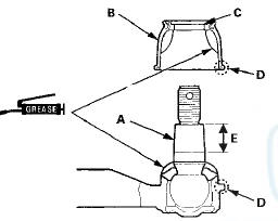
5. Pack the interior of the new ball joint boot (B) and lip (C) with fresh multipurpose grease.
Note these items when installing new grease: -Keep grease off the boot mounting area (D) and the tapered section (E) of the ball pin.
-Do not allow dust, dirt, or other foreign materials to enter the boot.
6. Install the ball joint boot (A) using the bearing driver attachment. The boot must not have a gap at the boot installation sections (B). After installing the boot, check the ball pin tapered section for grease contamination, and wipe it if necessary.
7. Install the tie-rod end to the rack end.
8. Connect the tie-rod end ball joint to the knuckle (see step 32 on page 17-64).
9. Check the wheel alignment, and adjust it if necessary (see page 18-5).
 Rack Guide Adjustment
Special Tools Required
Locknut Wrench, 40 mm 07MAA-SL00100 or Locknut
Wrench, 41 mm 07916-SA50001
1. Set the front wheels in the straight ahead position.
2. Loosen the rack guide screw locknut ( ...
 Gearbox Mount Cushion Replacement
1. Remove the steering gearbox (see page 17-37).
2. Position a 40 mm socket (A) on the flange part of the
gearbox housing with a washer (B), a 10 x 150 mm
flange bolt (C), and a 10 mm nut (D) as ...
See also:
EVAP Canister Replacement
1. Raise the vehicle on a lift.
2. Remove the wheel sensor harness clamps (A)
3. Support the rear subframe with a transmission jack
and a wooden block as shown.
4. Remove the rear subframe m ...
Vehicle Identification Number
Manufacturer, Make, and Type of Vehicle
1HG: Honda of America Mfg., Inc.
Honda passenger vehicle
Line, Body, and Engine Type
CS1: Accord Coupe/K24Z3
Body Type and Transmission Type
1: 2-door ...
Starter Overhaul
Disassembly/Reassembly
Armature Inspection and Test
1. Remove the starter (see page 4-11).
2. Disassemble the starter as shown in the Exploded
View.
3. Inspect the armature for wear or dama ...