 Honda Accord: Shift Solenoid Valve Removal and
Installation
Honda Accord: Shift Solenoid Valve Removal and
Installation
NOTE: -Do not hold the shift solenoid valve connector to remove and to install the shift solenoid valves. Hold the shift solenoid valve b o d y . -Do not install the shift solenoid valve A before installing the shift solenoid valve D, and do not Install shift solenoid valve B before shift solenoid valve E. If shift solenoid valves A and B are installed before shift solenoid valves D and E, it may damage the hydraulic control system.
1. Remove the shift solenoid valve mounting bolt, then remove the shift solenoid valves by holding the solenoid valve body. 2. Install new O-rings (two O-rings per shift solenoid valve) (F) on the shift solenoid valves.
NOTE: A new solenoid valve comes with new O-rings.
-If you install a new solenoid valve, use the O-rings provided with It.
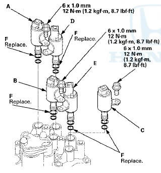
3. Install shift solenoid valve D by holding the shift solenoid valve body; be sure that the mounting bracket contacts the servo body.
4. install shift solenoid valve A by holding the shift solenoid valve body; be sure that the mounting bracket contacts the bracket on shift solenoid valve D.
5. Install shift solenoid valve E by holding the shift solenoid valve body; be sure that the mounting bracket contacts the servo body.
6. Install shift solenoid valve B by holding the shift solenoid valve body; be sure that the mounting bracket contacts the bracket on shift solenoid valve E.
7. Install shift solenoid valve C by holding the shiftsolenoid valve body; be sure that the mounting bracket contacts the servo body.
8. Install the shift solenoid valve mounting bolts.
 Servo Body Disassembly, Inspection,
and Reassembly
Servo Body Disassembly, Inspection,
and Reassembly
1. Clean all parts thoroughly in solvent, and dry them with compressed air.
Blow out all passages.
2. Inspect the valve body for scoring and damage.
3. Check shift valve D for free movement. I ...

See also:
DTC Troubleshooting Index
NOTE: Before you troubleshoot record all freeze data and any on-board
snapshot with the HDS, and review General
Troubleshooting Information (see page 14-4).
NOTE:
*1: The DTC in parentheses is ...
Special Tools
...