
 Honda Accord: Power Mirror Actuator Test
1. Remove the mirror mount cover (see page 20-62).
2. Disconnect the 8P connector (A) from the power mirror actuator (B).
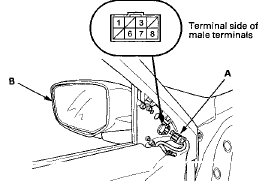
3. Check the actuator operation by connecting battery power and ground according to the table.
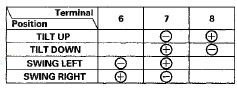
4. If the mirror fails to work properly, check for an open or high resistance in the wire between the connector and the mirror holder. If the wire is OK, replace the mirror actuator.
Defogger Test
5. Measure the resistance between terminals No. 1 and No. 3 of the 8P connector. There should be about 7 0 .
6. If the resistance is not as specified, check for an open or high resistance in the wire between the connector and the mirror holder. If the wire is OK, replace the mirror holder.
 Power Mirror Switch
Test/Replacement
Power Mirror Switch
Test/Replacement
1. Remove the power window master switch.
• 4-door (see page 22-305)
• 2-door (see page 22-306)
2. Disconnect the 13P connector from the power mirror
switch (A).
3. Check for contin ...
 Power Mirror Actuator Replacement
Removal
1. Remove the mirror holder (see page 20-63).
2. Remove the power mirror (see page 20-62), and
disconnect the power mirror 8P connector from the
door wire harness.
3. Remove the gaske ...
See also:
System Setup
This command group allows you to
change or customize HFL basic
settings.
To set a 4-digit passcode to lock the
HFL system for security purposes:
Press and release the HFL Talk
button before ...
System Description
Body Controller Area Network (B-CAN) and Fast Controller Area Network
(F-CAN)
The body controller area network (B-CAN) and the fast controller area network
(F-CAN) share information between
mult ...
Clutch Pedal Position Switch
Replacement
M/T model
1 Disconnect the clutch pedal position switch connector
(A).
2. Loosen the locknut (B), then remove the clutch pedal
position switch (C).
3. Install the clutch pedal position switch ...