 Honda Accord: Power Mirror Actuator Replacement
Removal
1. Remove the mirror holder (see page 20-63).
2. Remove the power mirror (see page 20-62), and disconnect the power mirror 8P connector from the door wire harness.
3. Remove the gasket (A).
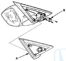
4 Remove the screws from the power mirror 8P connector (B).
5. Record the power mirror 8P connector terminal locations and wire colors.
6. Disassemble the power mirror 8P connector (A), and remove all terminals from it.
7. Remove the cover (A).
8. Remove the three screws, and separate the mirror housing (B) from the bracket (C).
9. Remove the screws and the actuator (A).
Installation
1. Route the wire harness (A) of a new actuator through the hole in the bracket (B).
2. Install the parts in the reverse order of removal.
3. Insert the new actuator terminals into the connector in the original arrangement.
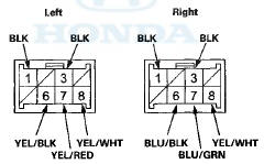
Terminal side of male terminals
4. Apply E P T sealer to the intersection of the wire harness and the 8P connector, then install the 8P connector in the reverse order of removal.
5. Install the gasket in the reverse order of removal.
6. Reassemble in the reverse order of disassembly.
NOTE: Be careful not to break the mirror when reinstalling it to the actuator.
7. Reinstall the mirror assembly on the door.
8. Operate the power mirror to ensure smooth operation.
 Power Mirror Actuator Test
1. Remove the mirror mount cover (see page 20-62).
2. Disconnect the 8P connector (A) from the power
mirror actuator (B).
3. Check the actuator operation by connecting battery
power and ground ...

See also:
Security System Alarm
The security system alarm activates when the doors, trunk, or hood are opened
without the key, remote transmitter, or smart entry system.
The security alarm continues for a maximum of two
minutes ...
Compass Zone Selection
1. Set the power mode to ON.
2. On the top screen of any audio source,
press and hold for 5
seconds.
- The display switches to the Compass
Settings screen.
3. Rotate to sele ...
Emissions Testing
Testing of Readiness Codes
If you take your vehicle for an
emissions test shortly after the
battery has been disconnected or
gone dead, it may not pass the test.
This is because of certain ‘ ...