 Honda Accord: Passenger's Under-dash Fuse/Relay
Box (MICU) Removal and
Installation
Honda Accord: Passenger's Under-dash Fuse/Relay
Box (MICU) Removal and
Installation
NOTE: SRS components are located in this area. Review the SRS component locations 4-door (see page 24-21), 2-door (see page 24-23), and precautions, and procedures (see page 24-25) before doing repairs or servicing.
Removal
1. Do the battery terminal disconnection procedure (see page 22-91).
2. Remove the passenger's kick panel: • 4-door (see page 20-107) • 2-door (see page 20-105) 3. Disconnect the connectors from the passenger's under-dash fuse/relay box (A).
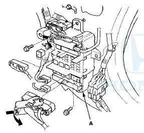
4. Loose the mounting bolt from the lower side of passenger's under-dash fuse/relay box.
5. Remove the mounting bolt from the upper side of passenger's under-dash fuse/relay box, and remove the passenger's under-dash fuse/relay box.
Installation
1. Install the relays and connect the connectors to the passenger's under-dash fuse/relay box, then install the passenger's under-dash fuse/relay box in the reverse order of removal.
2. Install the removed parts in the reverse order of removal.
3. Do the battery terminal reconnection procedure (see page 22-91).
4. Confirm that all systems work properly.
 Driver's Under-dash Fuse/Relay Box
(MICU) Removal and Installation
Driver's Under-dash Fuse/Relay Box
(MICU) Removal and Installation
Special Tools Required
Relay Puller 07AAC-000A1A0
USA models
NOTE; SRS components are located in this area. Review
the SRS component locations 4-door (see page 24-21),
2-door (see page 24-23), an ...
 Battery
...
See also:
Clutch Replacement
Special Tools Required
- Clutch Alignment Disc 07JAF-PM7011A
- Ring Gear Holder 07LAB-PV00100 or 07924-PD20003
- Clutch Alignment Tool Set 07PAF-0020000
- Clutch Alignment ...
Playing XM® Radio
• To Play the XM® Radio
1. Select the XM® mode.
2. Press the MENU button.
3. Rotate to select XM Tune
Mode, then press .
4. Rotate to select Channel
Mode or Category Mode, then p ...
Brake Fluid Level Switch Test
NOTE: If both the ABSA/SA indicator and the brake
system indicator come on at the same time, check the
VSA system for DTCs first (see page 19-48).
1. Disconnect the brake fluid level switch conne ...