 Honda Accord: Park Pin Switch Test
Produced in USA models
1. Remove the center console (see page 20-158).
2. Disconnect the A/T gear position indicator panel light/park pin switch 6P connector (A) from the park pin switch (B).
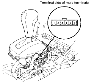
3. Check for continuity between connector terminals No.
1 and No. 2.
There should be continuity.
• There should be continuity when the shift lever is moved out of P.
• There should be continuity when the shift lever is moved to P.
4. If continuity is not as specified, replace the park pin switch (see page 14-258).
Produced In Saitama models .
1. Remove the center console (see page 20-158).
2. Disconnect the A/T gear position indicator panel light/park pin switch 6P connector (A) from the park pin switch (B).
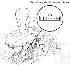
3. Check for continuity between connector terminals No.
1 and No. 2.
• There should be continuity when the shift lever is moved to P.
• There should be continuity when the shift lever is moved out of P.
4. In continuity is not as specified, replace the park pin switch (see page 14-258).
 Key Interlock Solenoid Test
NOTE: SRS components are located in this area. Review
the SRS component locations for 4-door (see page
24-21),for 2-door (see page 24-23), and the precautions
and procedures (see page 24-25) before ...
 Ignition Switch Test
NOTE: SRS components are located in the area. Review
the SRS component locations 4-door (see page 24-21),
2-door (see page 24-23), and precautions and
procedures (see page 24-25) before doing repai ...
See also:
ENGINE START/STOP Button
• Changing the Power Mode
ENGINE START/STOP Button Operating Range
You can start the engine when the smart entry
remote is inside the vehicle.
The engine may also run if the smart entry r ...
Tire Labeling
The tires that came on your vehicle
have a number of markings. Those
you should be aware of are described
below.
Tire Size
Whenever tires are replaced, they
should be replaced with tires o ...