 Honda Accord: Oil Pump Overhaul
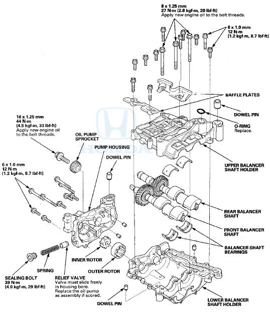
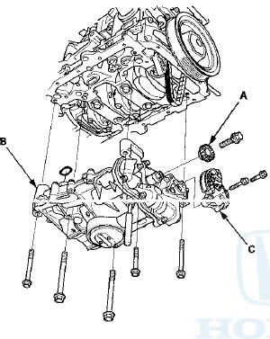
Exploded View
Oil Pump Removal
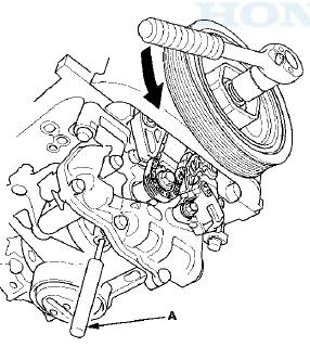
1. Turn the crankshaft pulley so its top dead center (TDC) mark (A) lines up with the pointer (B).
NOTE: The other pointer (C) is not used.
2. Remove the oil pan (see page 7-11).
3. To hold the rear balancer shaft, insert a 6 mm long pin punch (A) (Snap-on PPC108LA or equivalent) into the maintenance hole in the balancer shaft holder and through the rear balancer shaft.
4. Turn the crankshaft counterclockwise to compress the oil pump chain auto-tensioner.
5. Align the holes on the lock (A) and the oil pump chain auto-tensioner (B), then insert a 3.0 mm (0.12 in) diameter pin (C) into the holes. Turn the crankshaft clockwise to secure the pin.
6. Loosen the oil pump sprocket mounting bolt (A).
7. Remove the oil pump sprocket (A) and the oil pump (B) , then remove the oil pump chain auto-tensioner (C) .
Oil Pump Inspection
1. Remove the pump housing.
Then check the inner-to-outer rotor radial clearance between the inner rotor and the outer rotor.
If the inner-to-outer rotor radial clearance exceeds the service limit, replace the oil pump.
Inper Rotor-to-Outer Rotor Radial
Clearance
Standard (New): 0.050-”0.150 mm
(0.0020-0.0059 in)
Service Limit: 0.19 mm (0.007 in)
3. Check the pump housing-to-rotor axial clearance between the rotor (A) and the pump housing (B). If the pump housing-to-rotor axial clearance exceeds the service limit, replace the oil pump.
Pump Housing-to-Rotor Axial Clearance
Standard (New): 0.035-”0.070 mm
(0.0014-0.0028 in)
Service Limit: 0.12 mm (0.005 in)
4. Check the pump housing-to-outer rotor radial clearance between the outer rotor (A) and the pump housing (B). If the pump housing-to-outer rotor radial clearance exceeds the service limit, replace the oil pump.
Pump Housing-to-Outer Rotor Radial
Clearance
Standard (New): 0.150-”0.210 mm
(0.0059-0.0083 in)
Service Limit: 0.23 mm (0.009 in)
 Oil Jet Replacement
1. Remove the oil pump (see page 8-17).
2. Remove the baffle plate (see step 8 on page 7-14).
3. Remove the oil jet bolts (A), then remove the oil jets
(B).
4. Carefully install the oil jets ...
 Balancer Shaft Inspection
1. Seat the balancer shaft by pushing it away from the oil
pump sprocket end of the oil pump.
2. Zero the dial indicator against the end of the balancer
shaft, then push the balancer shaft back a ...
See also:
Fuel Line Inspection
Check the fuel system lines and hoses for damage, leaks, and deteriorationi,.
Replace any damaged parts.
Check all clamps, and make sure they are properly positioned and tightened.
All models ex ...
Security System Alarm
The security system alarm activates when the doors, trunk, or hood are opened
without the key, remote transmitter, or smart entry system.
The security alarm continues for a maximum of two
minutes ...
Protecting Child Passengers
Each year, many children are injured or killed in vehicle crashes because
they are
either unrestrained or not properly restrained. In fact, vehicle accidents are
the
number one cause of death ...