 Honda Accord: MICU input Test
NOTE: Before testing, troubleshoot the multiplex integrated control unit first, using B-CAN System Diagnosis Test Mode A (see page 22-134).
Driver's MICU
1. Turn the ignition switch to LOCK (0), and remove the driver's dashboard lower cover (see page 20-166).
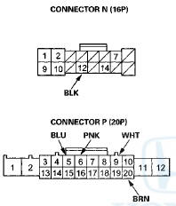
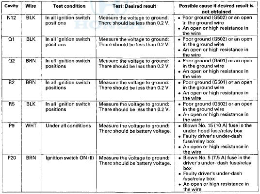
2. Disconnect driver's under-dash fuse/relay box connectors N, P, Q, and R.
NOTE: All connector views are wire side of female terminals.
3. Inspect the connector and socket terminals to be sure they are all making good contact.
• If the terminals are bent, loose or corroded, repair them as necessary and recheck the system.
• If the terminals look OK, go to step 4.
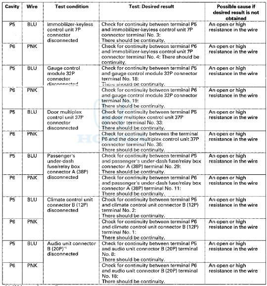
4. With the connectors still disconnected, do these input tests at the following connectors.
• If any test indicates a problem, find and correct the cause, then recheck the system.
• If all the input tests prove OK, go to step 5.
*1: With premium audio system
*2: With HandsFreeLink
*1: With premium audio system
*2: With HandsFreeLink
5. Reconnect the connectors to the driver's under-dash fuse/relay box, turn the ignition switch to ON (II), and do these input tests at the following connectors.
• If any test indicates a problem, find and correct the cause, then recheck the system.
• If all the input tests prove OK, go to step 6.
NOTE: These are power and ground tests for the multiplex integrated control unit.
Passenger's MICU
6. Turn the ignition switch to LOCK (0), and remove the passenger's kick panel.
• 2-door (see page 20-105)
• 4-door (see page 20-107)
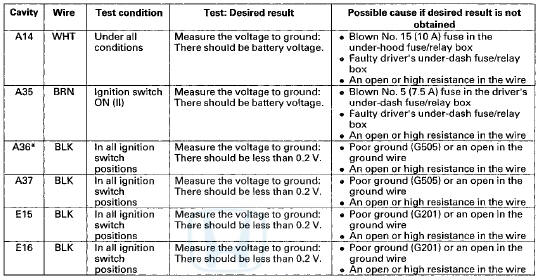
7. Disconnect passenger's under-dash fuse/relay box connectors A and E.
NOTE: All connector views are wire side of female terminals.
*: "08-09 models
8. Inspect the connector and socket terminals to be sure they are all making good contact.
• If the terminals are bent, loose or corroded, repair them as necessary and recheck the system.
• If the terminals look OK, go to step 9.
9. Reconnect the connectors to the passenger's under-dash fuse/relay box, turn the Ignition switch to ON (II), and do these input tests at the following connectors.
• If any test indicates a problem, find and correct the cause, then recheck the system.
• If all the input tests prove OK, go to step 10.
*: '08-09 models
10. If multiple failures are found on more than one control unit, replace the driver's under-dash fuse/relay box (includes the driver's MICU).
• USA models (see page 22-86) • Canada models (see page 22-87) If input failures are related to a particular control unit, replace the control unit.
 DTC Troubleshooting
DTC B10A2: Driver's MICU (EEPROM) Error
NOTE: If you are troubleshooting multiple DTCs, be sure
to follow the instructions in B-CAN System Diagnosis
Test Mode A (see page 22-134).
1. Clear the D ...

See also:
DTC Troubleshooting
DTC P0443: EVAP Canister Purge Valve Circuit
Malfunction
Special Tools Required
Vacuum Pump/Gauge, 0 - 3 0 In.Hg, Snap-on YA4000A
or equivalent commercially available
NOTE: Before you troubleshoo ...
Engine Oil Additives
Your vehicle does not require any oil
additives. Additives may adversely
affect the engine or transmission
performance and durability. ...
Heating and Cooling
Using Vents, Heating and A/C
• Heating
The heater uses engine coolant to warm the
air.
1. Adjust the fan speed using the fan control
dial.
2. Select .
3. Adjust the temperature using ...