 Honda Accord: DTC Troubleshooting
DTC B10A2:
Driver's MICU (EEPROM) Error
NOTE: If you are troubleshooting multiple DTCs, be sure to follow the instructions in B-CAN System Diagnosis Test Mode A (see page 22-134).
1. Clear the DTCs with the HDS.
2. Turn the ignition switch to LOCK (0) and then back to ON (II).
3. Wait for at least 6 seconds.
4. Check for DTCs with the HDS.
Is DTC B10A2 Indicated? YES
-Faulty driver's MICU; replace the driver's under-dash fuse/relay box, USA models (see page 22-86), Canada models (see p a g e 22-87).
NO
-lntermittent failure, the system is OK at this time.
DTC B11A2:
Passenger's MICU Internal (EEPROM) Error
NOTE: If you are troubleshooting multiple DTCs, be sure to follow the instructions in B-CAN System Diagnosis Test Mode A (see page 22-134).
1. Clear the DTCs with the HDS.
2. Turn the ignition switch to LOCK (0) and then back to ON (II).
3. Wait for at least 6 seconds.
4. Check for DTCs with the HDS.
Is DTC B11A2 indicated? YES
-Faulty passenger's MICU; replace the passenger's under-dash fuse/relay box (see page 22-89).
NO
-lntermittent failure, the system is OK at this time.
DTC B1036:
Driver's MICU IG1 .Line Input Error
NOTE; • Before troubleshooting check the No. 5 (7.5 A) fuse in the driver's under-dash fuse/relay box.
• If you are troubleshooting multiple DTCs, be sure to follow the instructions in B-CAN System Diagnosis Test Mode A (see page 22-134).
1. Clear the DTCs with the HDS.
2. Turn the ignition switch to LOCK (0) and then back to ON (II).
3. Wait for at least 6 seconds.
4. Check for DTCs with the HDS.
Is DTC B1036 indicated? YES
-Go to step 5.
NO
-lntermittent failure, the system is OK at this time.
Check for loose or poor connections at the driver's under-dash fuse/relay box connector C (5P). If the connections are good, check the battery condition (see page 22-90) and the charging system.
5. Measure the voltage between gauge control module 32P connector terminal No. 32 and body ground.
GAUGE CONTROL M O D U L E 32P CONNECTOR
Wire side of female terminals
Is there battery voltage? YES-
Faulty driver's MICU; substitute a known-good driver's under-dash fuse/relay box and recheck.
NO
-Repair an open or high resistance in the wire between the driver's under-dash fuse/relay box and gauge control module.
DTC B11C7:
Passenger's MICU IG1 Line Input Error
NOTE: • Before troubleshooting check the No. 5 (7.5 A) fuse in the driver's under-dash fuse/relay box.
• If you are troubleshooting multiple DTCs, be sure to follow the instructions in B-CAN System Diagnosis Test Mode A (see page 22-134).
1. Clear the DTCs with the HDS.
2. Turn the ignition switch to LOCK (0) and then back to ON (II).
3. Wait for at least 6 seconds.
4. Check for DTCs with the HDS.
Is DTC B11C7 indicated? YES
-Go to step 5.
NO
-lntermittent failure, the system is OK at this time.
Check for loose or poor connections. If the connections are good, check the battery condition (see page 22-90) and the charging system.
5. Check the DTCs with the HDS.
Is DTC B11C7 indicated with DTC U1282? YES
-Go to DTC U1282 troubleshooting (see page 22-291 ).
NO
-Go to step 6.
6. Turn the ignition switch to LOCK (0).
7. Disconnect passenger's under-dash fuse/relay box connector A (38P).
8. Turn the ignition switch to ON (II).
9. Measure the voltage between passenger's under-dash fuse/relay box connector A (38P) terminal No. 35 and body ground.
P A S S E N G E R ' S U N D E R - D A S H FUSE/RELAY BOX CONNECTOR A (38P)
Wire side of female terminals
Is there battery voltage? YES
-Faulty passenger's MICU; substitute a known-good passenger's under-dash fuse/relay box and recheck.
NO
-Repair an open or high resistance in the wire between the passenger's under-dash fuse/relay box and driver's under-dash fuse/relay box.
DTC U0155:
Driver's MICU Lost Communication With Gauge Control Module
NOTE: If you are troubleshooting multiple DTCs, be sure to follow the instructions in B-CAN System Diagnosis Test Mode A (see page 22-134).
1 . Clear the DTCs with the HDS.
2. Turn the ignition switch to LOCK (0) and then back to ON (II).
3. Wait for at least 6 seconds.
4. Check for DTCs with the HDS.
Is DTC U0155 Indicated? YES-
Go to the gauge control module input test and do ail p o w e r , g r o u n d , and communication input tests (see page 22-347). If the tests prove OK, replace the gauge control module (see page 22-351 ) . NO
-lntermittent failure, the system is OK at this time.
Check for loose or poor connections at the gauge control module (32P) and the related u n i t s.
DTC U0155:
Passenger's MICU Lost Communication With Gauge Control Module
NOTE: If you are troubleshooting multiple DTCs, be sure to follow the instructions in B-CAN System Diagnosis Test Mode A (see page 22-134).
1. Clear the DTCs with the HDS.
2. Turn the ignition switch to LOCK (0) and then back to ON (II).
3. Wait for at least 6 seconds.
4. Check for DTCs with the HDS.
Is DTC U0155 Indicated? YES
-Go to the gauge control module input test, and do all power, ground, and communication input tests (see page 22-347). If the tests prove OK, replace the gauge control module (see page 22-351 ) . NO
-lntermittent failure, the system is OK at this time.
Check for loose or poor connections at the gauge control module (32P) and the related units.
DTC U0199:
Driver's MICU Lost Communication With Door Multiplex Control Unit
NOTE: If you are troubleshooting multiple DTCs, be sure to follow the instructions in B-CAN System Diagnosis Test Mode A (see page 22-134).
1. Clear the DTCs with the HDS.
2. Turn the ignition switch to LOCK (0) and then back to ON (II).
3. Wait for at least 6 seconds.
4. Check for DTCs with the HDS, is DTC U0199 indicated? YES
-Go to the door multiplex control unit input test, and do all power, ground, and communication input test (see page 22-151 )s. If the tests prove OK, replace the power window master switch, 4-door (see page 22-305), 2-door (see page 22-306).
NO
-lntermittent failure, the system is OK at this time.
Check for loose or poor connections at the door multiplex control unit 37P connector and the related units.
DTC U1280:
Communication Bus Line Error (BUS-OFF)
1. Clear the DTCs with the HDS.
2. Turn the ignition switch to LOCK (0) and then back to ON (II).
3. Wait for at least 6 seconds.
4. Check for DTCs with the HDS.
Is DTC U1280 indicated? YES
-Go to step 5.
NO
-lntermittent failure, the system is OK at this time.
Check for loose or poor connections, or worn/shorted wires. If the connections are good, check the battery condition (see page 22-90) and the charging system.
5. Turn the ignition switch to LOCK (0).
6. Disconnect the appropriate connector at each control unit in the table one at a time. Clear the DTC, then recheck for DTCs after each unit is disconnected.
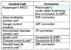
*1: With premium audio system
*2: With climate control system
*3: With HandsFreeLink
Is DTC U1280 indicated with each individual unit disconnected? YES
-Leave the connectors disconnected, and go to step 7.
NO
-Go to the input test for the control unit that was disconnected when DTC U1280 did not reset and do all power and ground input tests. If the tests prove OK, replace that unit.
• Passenger's MICU input test (see page 22-154).
• Gauge control module input test (see page 22-347).
• Door multiplex control unit input test (see page 22- 292).
• Climate control unit input test (see page 21-172).
• Immobilizer-keyless control unit input test (see page 22-437).
• HandsFreeLink control unit input test (see page 23- 266).
7. Turn the ignition switch to LOCK (0).
8. Disconnect each control unit connector in the table.
*1: With premium audio system
*2: With climate control system
*3: With HandsFreeLink
9. Disconnect driver's under-dash fuse/relay box connector P (20P).
10. Check for continuity between driver's under-dash fuse/relay box connector P (20P) terminals No. 5 and No. 6.
DRIVER'S UNDER-DASH FUSE/RELAY BOX CONNECTOR P (20P)
Wire side of female terminals
Is there continuity? YES
-Repair a short between the B-CAN w i r e s . NO
-Go to step 11.
11. Check for continuity between body ground and driver's under-dash fuse/relay box connector P (20P) terminals No. 5 and No. 6 individually.
DRIVER'S UNDER-DASH FUSE/RELAY BOX CONNECTOR P (20P)
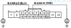
Wire side of female terminals
Is there continuity? YES-
Repair a short to ground in the wire.
NO
-Go to step 12.
12. Turn the ignition switch to ON (II).
13. Measure the voltage between body ground and driver's under-dash fuse/relay box connector P (20P) terminals No. 5 and No. 6 individually.
DRIVERS UNDER-DASH FUSE/RELAY BOX CONNECTOR P (20P)
Wire side of female terminals
Is there voltage? YES
-Repair a short to power in the wire.
NO-
Faulty driver's MICU, replace the driver's under-dash fuse/relay box, USA models (see page 22-86), Canada models (see page 22-87).
DTC U1282:
Passenger's MICU Lost Communication With Driver's MICU
NOTE: If you are troubleshooting multiple DTCs, be sure to follow the instructions in B-CAN System Diagnosis Test Mode A (see page 22-134).
1. Clear the DTCs with the HDS.
2. Turn the ignition switch to LOCK (0) and then back to ON (II).
3. Wait for at least 6 seconds.
4. Check for DTCs with the HDS.
Is DTC U1282 indicated? YES
-Go to the driver's MICU input test, and do all power, ground, and communication input tests (see page 22-151). If the tests prove OK, replace the driver's under-dash fuse/relay box, USA models (see page 22-86), Canada models (see page 22-87).
NO-
lntermittent failure, the system is OK at this time.
Check for loose or poor connections at driver's under-dash fuse/relay box connector P (20P) and the related units.
DTC U1283:
Driver's MICU Lost Communication With Passenger's MICU
NOTE: If you are troubleshooting multiple DTCs, be sure to follow the instructions in B-CAN System Diagnosis Test Mode A (see page 22-134).
1. Clear the DTCs with the HDS.
2. Turn the ignition switch to LOCK (0) and then back to ON (II).
3. Wait for at least 6 seconds.
4. Check for DTCs with the HDS.
is DTC U1283 indicated? YES
-Go to the passenger's MICU input test, and do all power, ground, and communication input tests (see page 22-154). If the tests prove OK, replace the driver's under-dash fuse/relay box, USA models (see page 22-86), Canada models (see page 22-87).
NO
-lntermittent failure, the system is OK at this time.
Check for loose or poor connections at driver's under-dash fuse/relay box connector P (20P) and the related units.
 Circuit Diagram
...
 MICU input Test
NOTE: Before testing, troubleshoot the multiplex integrated control unit
first, using B-CAN System Diagnosis Test Mode
A (see page 22-134).
Driver's MICU
1. Turn the ignition switch to LOCK (0), ...
See also:
Training HomeLink
Before you begin - If you just
received your vehicle and have not
trained any of the buttons in
HomeLink before, you should erase
any previously learned codes before
training the first butto ...
XM Antenna Replacement
1. Remove the headliner (see page 20-140).
2. Remove the nut (A) from the XM antenna (B).
3. Disconnect the connector (C) and remove the XM
antenna.
4. Install the XM antenna in the reverse ...
Memorizing the Tire Pressure Sensor ID
Special Tools Required
TPMS Trigger Tool ATEQ VT55*
- Available through the Honda Tool and Equipment
Program 888-424-6857
All four tire pressure sensor IDs must be memorized to
the TPMS control u ...