 Honda Accord: Intake Manifold Removal and Installation
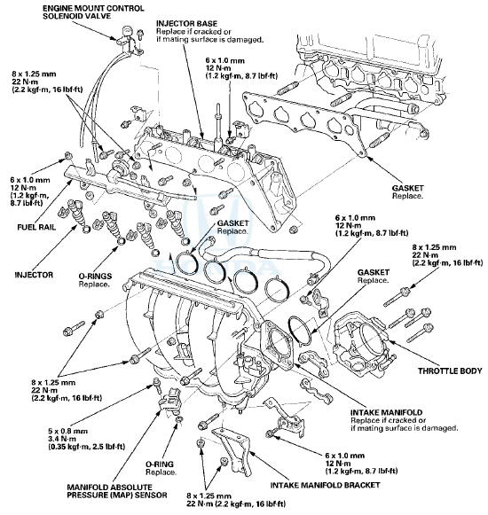
Exploded View
Removal
1. Do the battery removal procedure (see page 22-92).
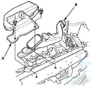
2. Remove the front grille cover: Р’В© 2-door (see page 20-274) Р’В© 4-door (see page 20-274) 3. Remove the water separator (A) and the intake air duct (B).
4. Remove the harness clamps, then remove the battery base (see step 8 on page 5-3).
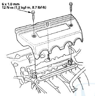
5. Remove the engine cover.
6. Disconnect the breather pipe (A), then remove the intake air duct (B).
7, Disconnect the evaporative emission (EVAP) canister
hose (A) and the brake booster vacuum hose (B).
8. Disconnect the water bypass hoses (C), then plug the
water bypass hoses.
10. Remove the intake manifold bracket
11. Disconnect the vacuum hose (A) from the intake
manifold.
12. Remove the Intake manifold (A), then disconnect the positive crankcase ventilation (PCV) hose (B) from the Intake manifold.
Installation
1. Connect the positive crankcase ventilation (PCV) hose (A) to the intake manifold, then install the intake manifold (B) with new gaskets (C), and tighten the bolts and nuts in a crisscross pattern in three steps, beginning with the inner bolt.
2. Connect the vacuum hose (A) to the intake manifold.
3. Install the intake manifold bracket.
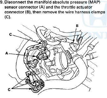
4. Connect the manifold absolute pressure (MAP) sensor connector (A) and the throttle actuator connector (B), then install the wire harness clamps (C).
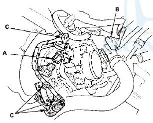
5. Connect the water bypass hoses (A).
6. Connect the evaporative emission (EVAP) canister hose (B) and the brake booster vacuum hose (C).
7. Install the intake air duct (A), then connect the breather pipe (B).
NOTE: When tightening the screw of the hose band (C), align the edge of the hose band (D) with the mark (E) painted on the hose band. If you tighten the screw over the mark, replace the hose band.
8. Install the engine cover.
9. Install the battery base, then install the harness clamps {see step 63 on page 5-22).
10. Install the water separator (A) and the intake air duct (B).
11. Install the front grille cover: - 2-door (see page 20-274) - 4-door (see page 20-274) 12. Do the battery installation procedure (see page 22-92).
13. After installation, check that all tubes, hoses, and connectors are installed correctly.
14. Clean up any spilled engine coolant.
15. Refill the radiator with engine coolant, and bleed the air from the cooling system (see step 5 on page 10-6).

 Exhaust Pipe and Muffler Replacement
NOTE: Use new gaskets and self-locking nuts when reassembling.
...
See also:
Secondary H02S Replacement
Special Tools Required
02 Sensor Wrench Snap-on S6176 or equivalent,
commercially available
1. Disconnect the secondary H02S 4P connector (A),
then remove the secondary H02S (B).
2. Install the ...
Rear Window Replacement
NOTE:
- Put on gloves to protect your hands.
- Wear eye protection while cutting the glass adhesive
with a piano wire.
- Use seat covers to avoid damaging any surfaces.
- Do not damage the ...
Knuckle/Hub Bearing Unit Replacement
Exploded View
Special Tools Required
- Ball Joint Thread Protector, 14 mm
07AAE-SJAA100
- Ball Joint Remover, 32 mm 07MAC-SL0A102
Hub Bearing Unit Replacement
1. Raise and support the vehicle ...